
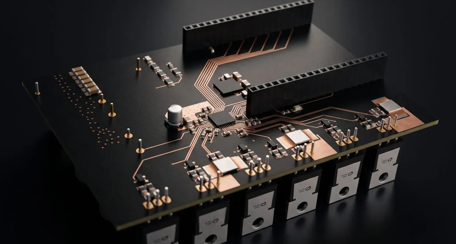
ESC Motor Driver Board
DRV8353 motor driver stage driven by an STM32 controller.
The brief
A three-phase inverter is a power stage, not a logic board. Everything on this design — the gate driver, the six-MOSFET bridge, the current and bus sensing — exists to move real current while giving the separate controller board a clean signal to work with.
The hard part is the commutation loop. Keeping that loop physically small and away from the sense and control paths is what stops a high-power stage from injecting its own switching noise back into the measurements that close the loop.

What we did
A high-power, three-phase inverter board for driving brushless (BLDC/PMSM) motors. It is a power stage that plugs into a separate controller board, which supplies the PWM signals and reads back the current and voltage measurements.
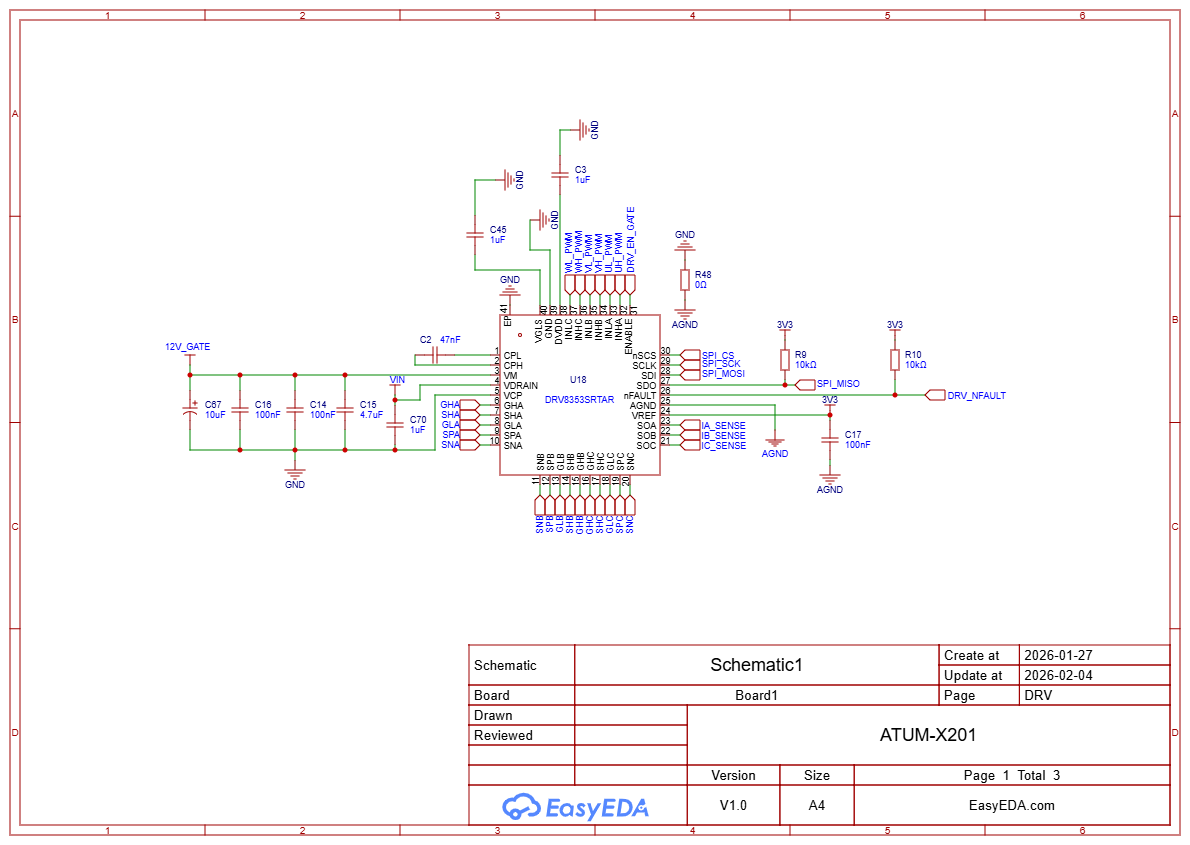
- Smart gate driver: A DRV8353S three-phase driver with SPI configuration controls the MOSFET gates. It provides charge-pump supplies, built-in current-sense amplifiers and fault reporting (nFAULT) back to the controller.
- Six-MOSFET power stage: Three half-bridges use NTP5D0N15MC 150 V MOSFETs. Each gate has a series resistor and a Schottky diode in parallel with a second resistor, which lets turn-on and turn-off speeds be tuned separately. Pull-down resistors keep the MOSFETs off safely.
- Phase current sensing: A 0.5 mΩ shunt resistor on each low side feeds the driver’s amplifiers through Kelvin-style filtered sense lines, giving per-phase current measurements.
- Bus voltage sensing: A resistor divider scales the DC bus voltage to a measurable level for the controller.
- Power input filtering: Two 470 µF bulk capacitors plus a bank of 100 nF and 1 µF ceramics keep the DC bus stable under fast switching.
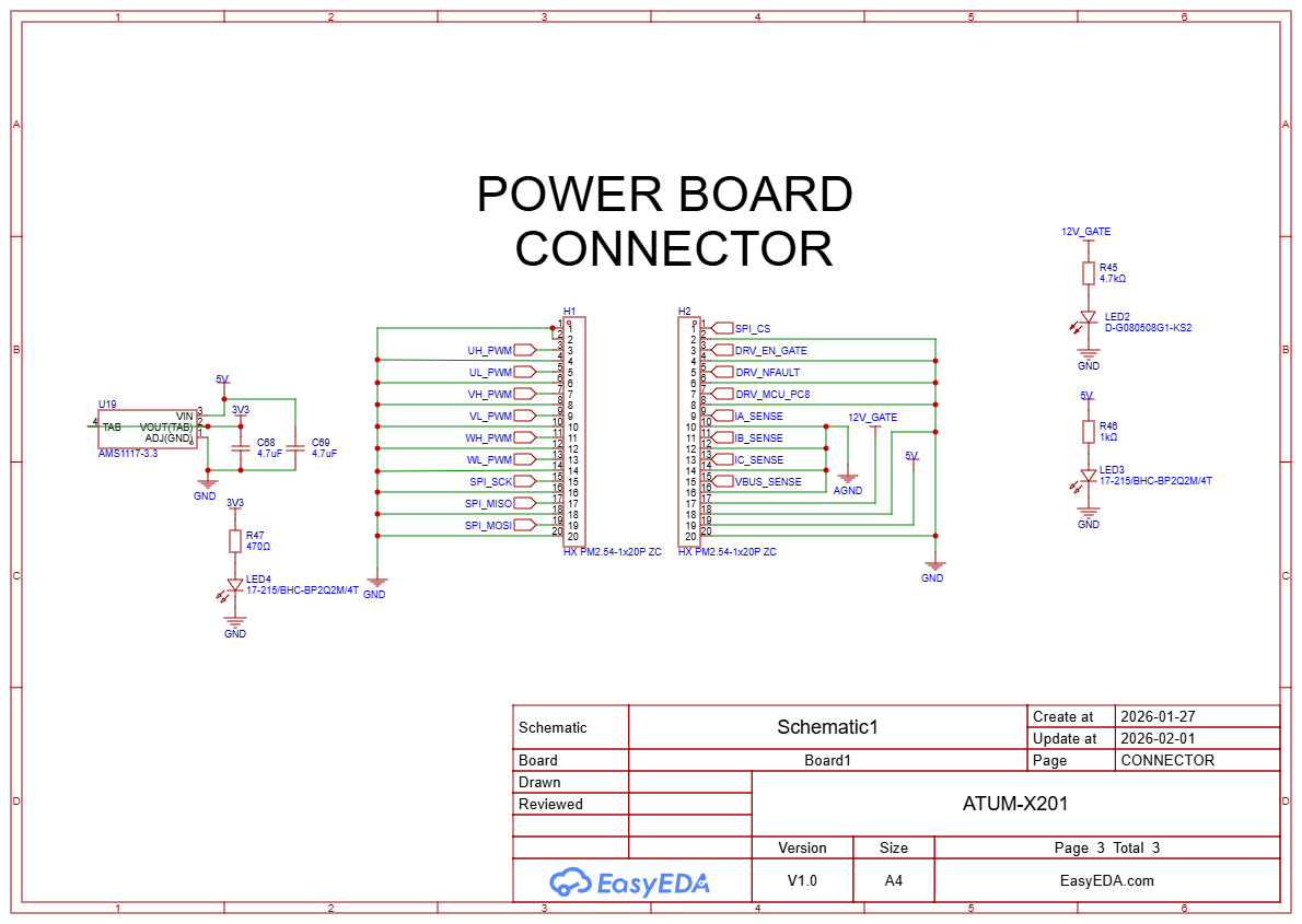
- Controller interface: Two 20-pin headers carry the six PWM inputs, SPI, driver enable, fault signal, the three phase-current signals and the bus voltage signal, plus power rails.
- On-board power and indicators: An AMS1117-3.3 regulator provides logic power, and status LEDs show the 5 V, 12 V gate and 3.3 V rails.
Design details



Design summary
| CAD tool | EasyEDA |
|---|---|
| Overview | A high-power, three-phase inverter board for driving brushless (BLDC/PMSM) motors. |
| Smart gate driver | A DRV8353S three-phase driver with SPI configuration controls the MOSFET gates. |
| Six-MOSFET power stage | Three half-bridges use NTP5D0N15MC 150 V MOSFETs. |
| Phase current sensing | A 0.5 mΩ shunt resistor on each low side feeds the driver’s amplifiers through Kelvin-style… |
| Bus voltage sensing | A resistor divider scales the DC bus voltage to a measurable level for the controller. |
| Power input filtering | Two 470 µF bulk capacitors plus a bank of 100 nF and 1 µF ceramics keep the DC bus stable… |
| Controller interface | Two 20-pin headers carry the six PWM inputs, SPI, driver enable, fault signal, the three… |
| On-board power and indicators | An AMS1117-3.3 regulator provides logic power, and status LEDs show the 5 V, 12 V gate and 3.3… |
Have a board like this?
Send us the schematic, the mechanical constraints and the deadline. We will tell you what it takes and what it costs.