
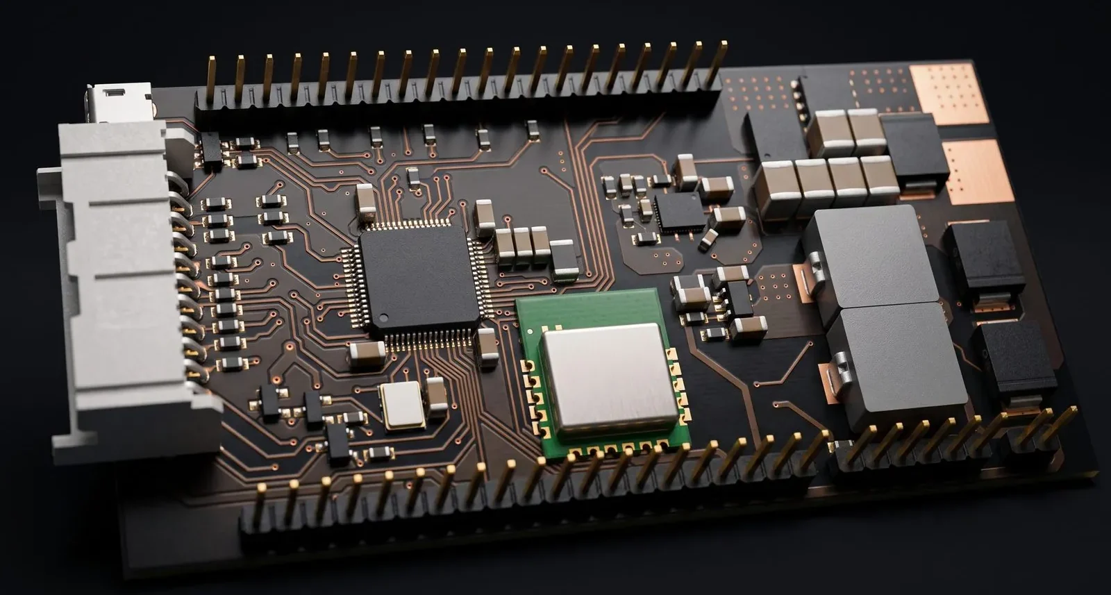
ESC Controller Board (STM32)
STM32 MCU board with full throttle and brake I/O for an electric-bike ESC.
The brief
A two-board BLDC controller splits one job across two PCBs, and this is the half that has to live in the middle of both worlds. It carries every signal the rider and the vehicle actually touch, while the motor phases and the high-current supply live on the power board across two board-to-board connectors.
The design problem is isolation of consequence rather than voltage: the logic and auxiliary rails have to stay usable while the power board switches hard, and the connectors between them have to survive mis-alignment of the two halves.
What we did
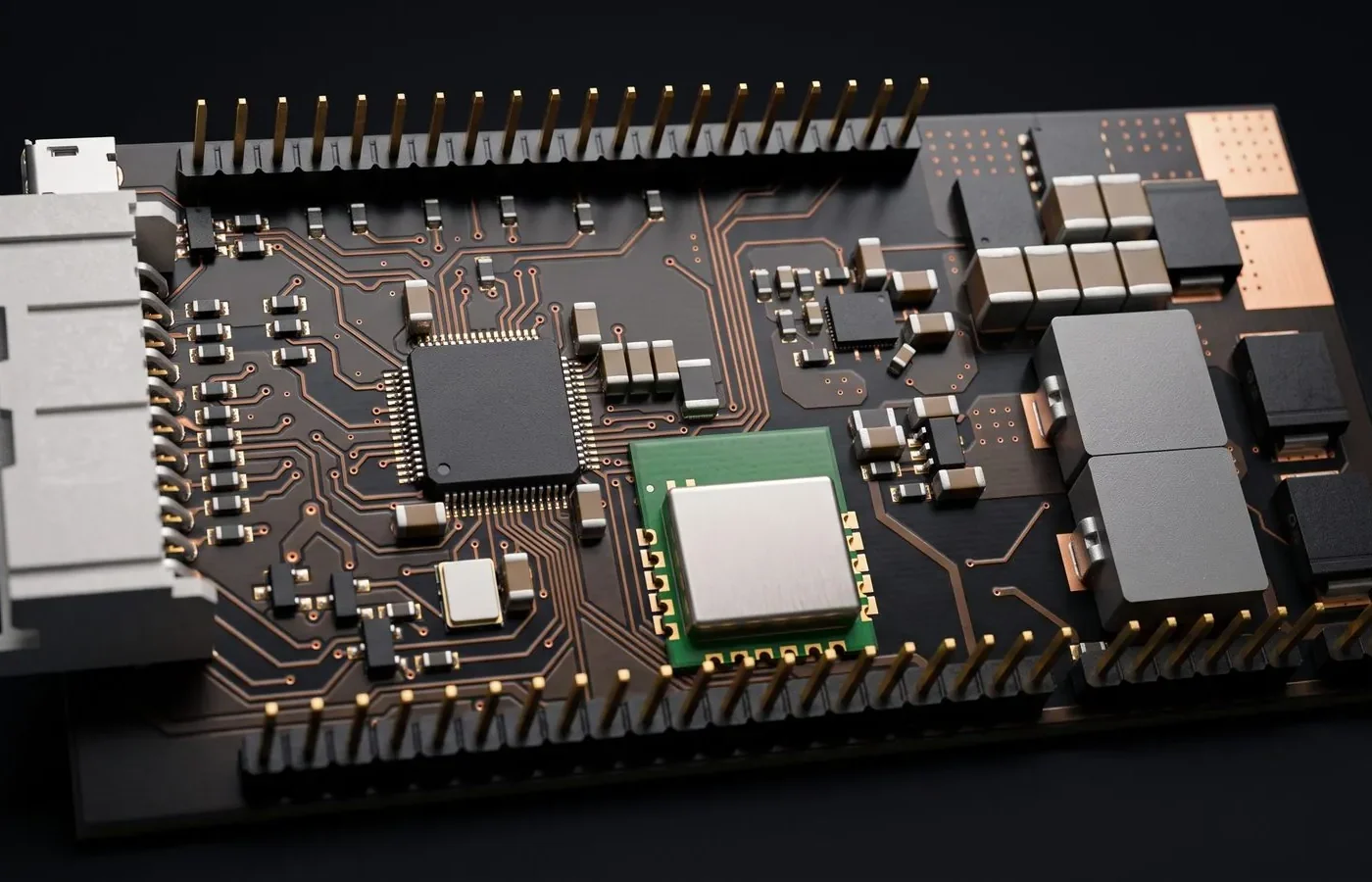
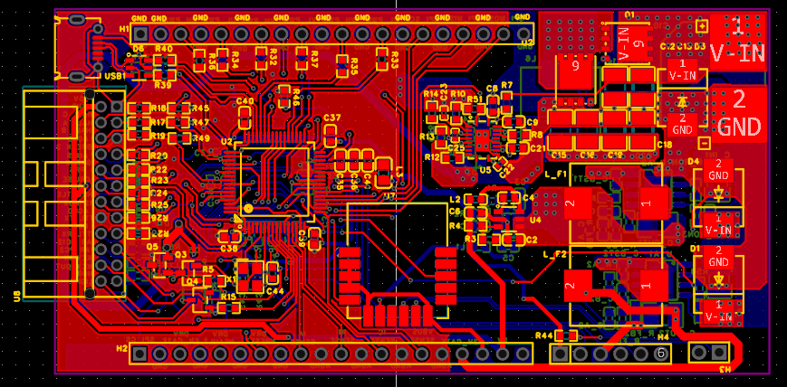
The control and interface board of a two-board brushless motor controller. It mates with the ATUM-X201 three-phase power board through two 20-pin board-to-board connectors. This board runs the control firmware, reads the rider and motor inputs, and supplies the logic and auxiliary power rails.
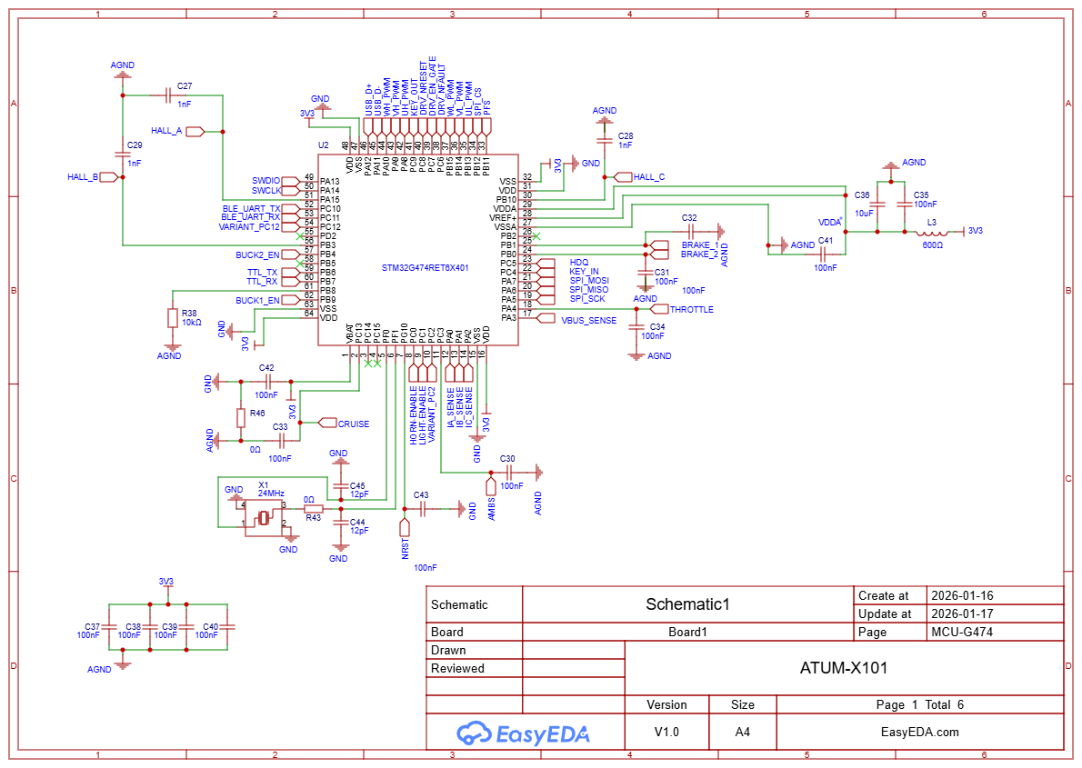
- Main controller: An STM32G474RET6 (Cortex-M4, motor-control focused) with a 24 MHz crystal. It generates the six PWM signals, configures the gate driver over SPI, and reads phase currents, bus voltage and Hall sensors.
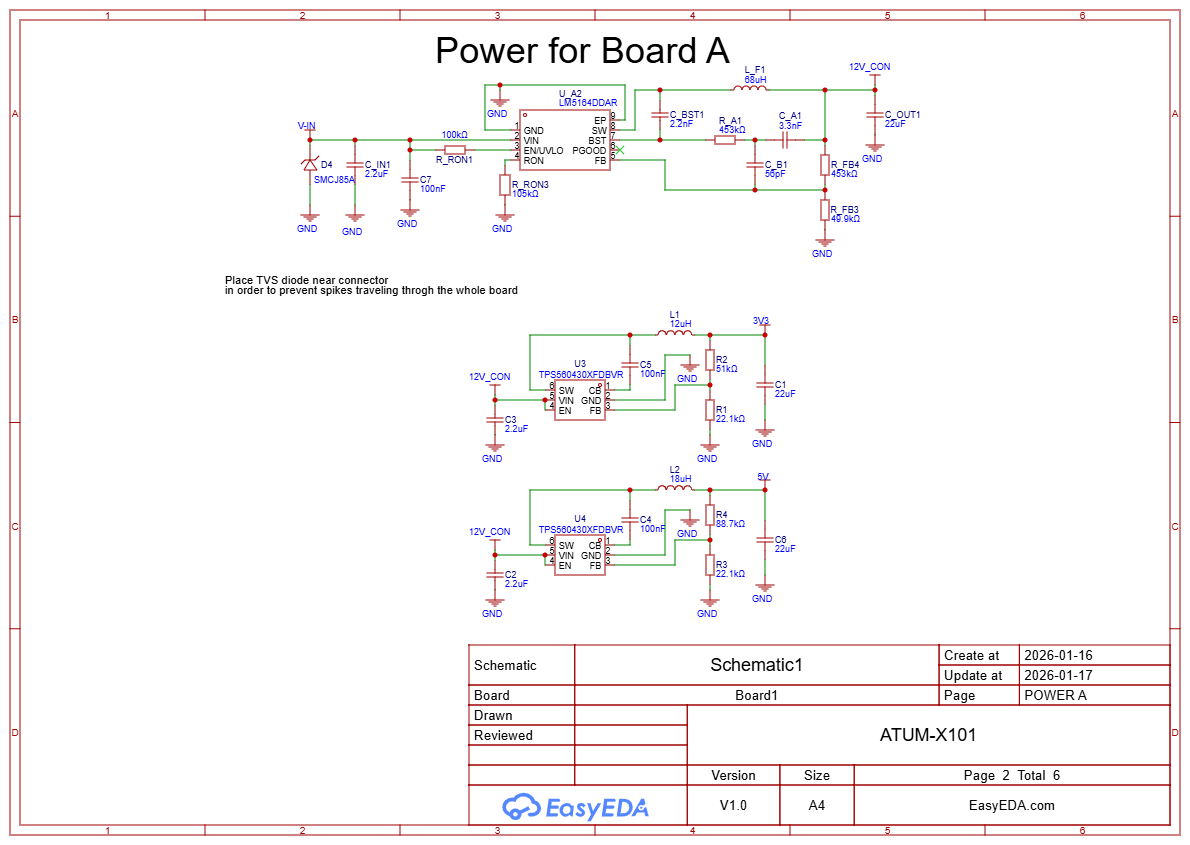
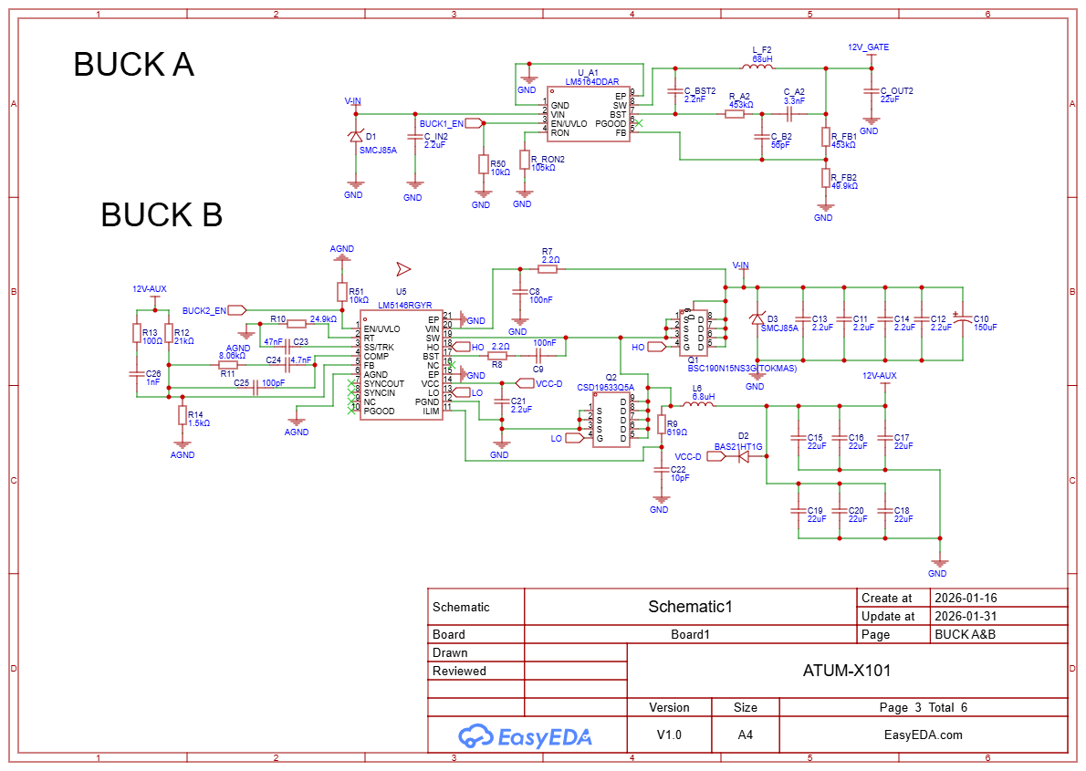
- Multi-stage power supply: A wide-input LM5164 buck converter makes a 12 V gate-drive rail, an LM5146 synchronous buck controller with external MOSFETs makes a higher-current 12 V auxiliary rail, and two TPS560430 converters make the 5 V and 3.3 V logic rails. A TVS diode on the input suppresses voltage spikes.
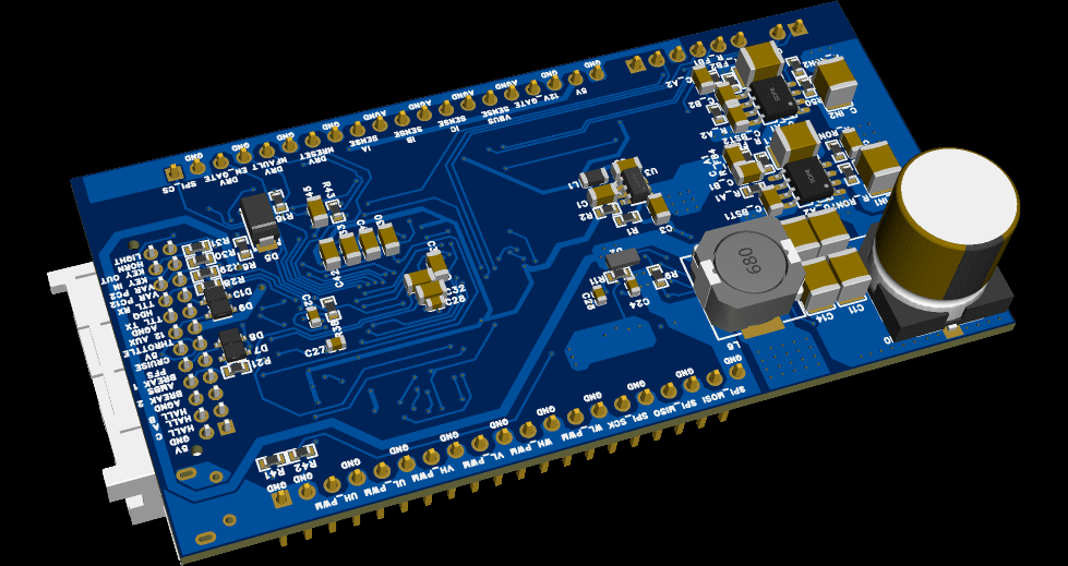
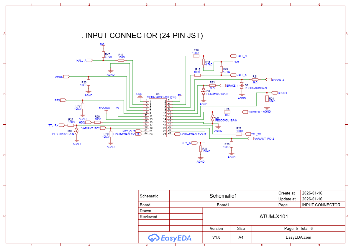
- Rider and vehicle inputs: A 24-pin JST connector brings in three Hall sensors, throttle, two brake inputs, cruise, ignition key and other signals, all with series resistors, pull-ups and ESD protection diodes.
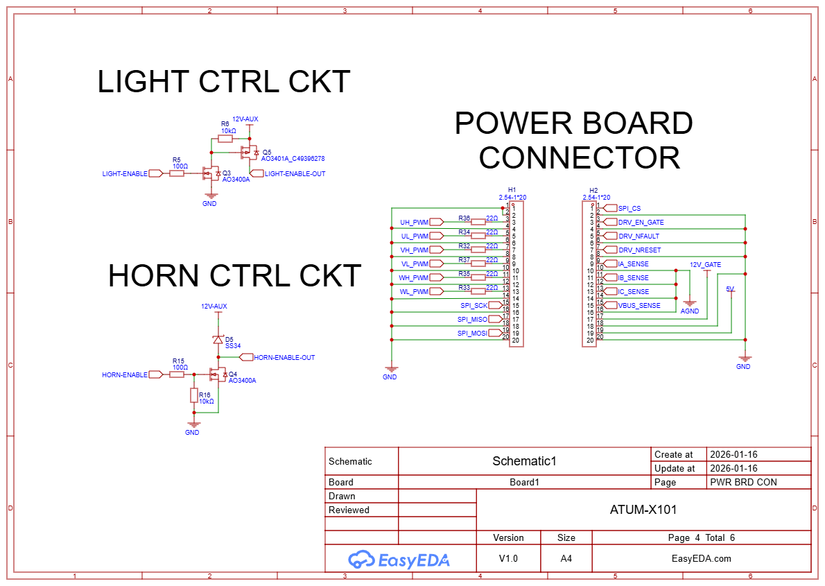
- Accessory control: MOSFET switch circuits control a horn and lights from the MCU.
- Power board interface: Two 20-pin headers carry the PWM signals, SPI, driver enable and fault lines, current and voltage sense signals, and power rails to the ATUM-X201.
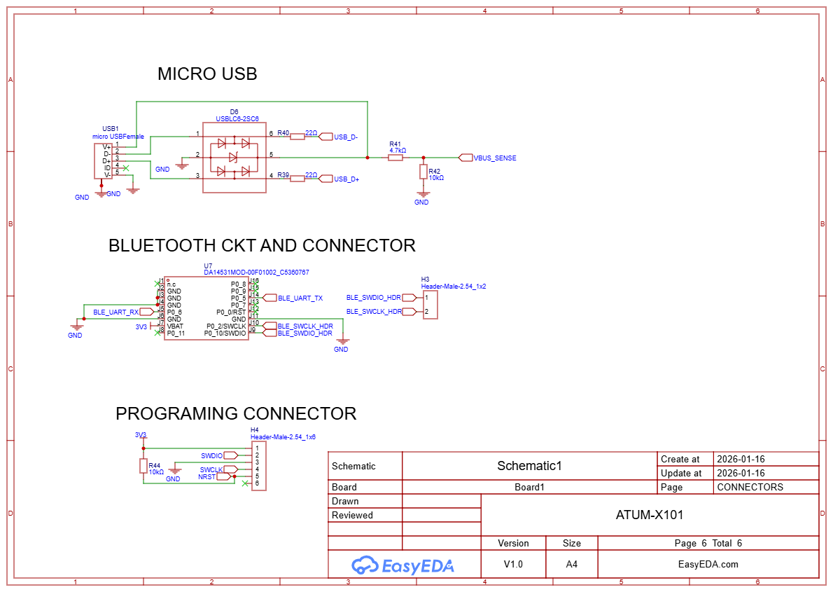
- Connectivity: A micro-USB port with ESD protection, a DA14531 Bluetooth Low Energy module for wireless tuning or monitoring, and a UART/HDQ line for battery communication.
- Programming: A 6-pin SWD header for the STM32 and a separate header for the Bluetooth module.
Design details

Design summary
| CAD tool | EasyEDA |
|---|---|
| Overview | The control and interface board of a two-board brushless motor controller. |
| Main controller | An STM32G474RET6 (Cortex-M4, motor-control focused) with a 24 MHz crystal. |
| Multi-stage power supply | A wide-input LM5164 buck converter makes a 12 V gate-drive rail, an LM5146 synchronous buck… |
| Rider and vehicle inputs | A 24-pin JST connector brings in three Hall sensors, throttle, two brake inputs, cruise,… |
| Accessory control | MOSFET switch circuits control a horn and lights from the MCU. |
| Power board interface | Two 20-pin headers carry the PWM signals, SPI, driver enable and fault lines, current and… |
| Connectivity | A micro-USB port with ESD protection, a DA14531 Bluetooth Low Energy module for wireless… |
| Programming | A 6-pin SWD header for the STM32 and a separate header for the Bluetooth module. |
Have a board like this?
Send us the schematic, the mechanical constraints and the deadline. We will tell you what it takes and what it costs.