
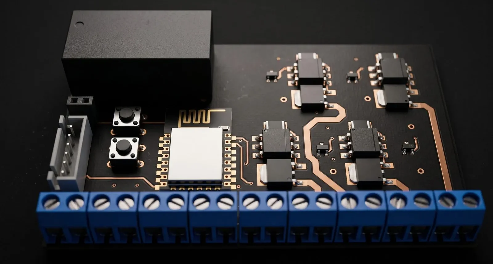
Home Automation Hub (ESP8266 NodeMCU)
Controls up to eight devices from a mobile app built in MIT App Inventor.
The brief
Eight switched mains outputs and eight inputs on one board doubles the isolation and doubles the wiring risk of the four-channel version. The mains side has to be treated as a separate circuit that happens to share a board with the ESP-12E.
The inputs are the quieter half of the problem but the easier one to get wrong in a way that only shows up in service, so they are protected individually rather than as a group.
What we did
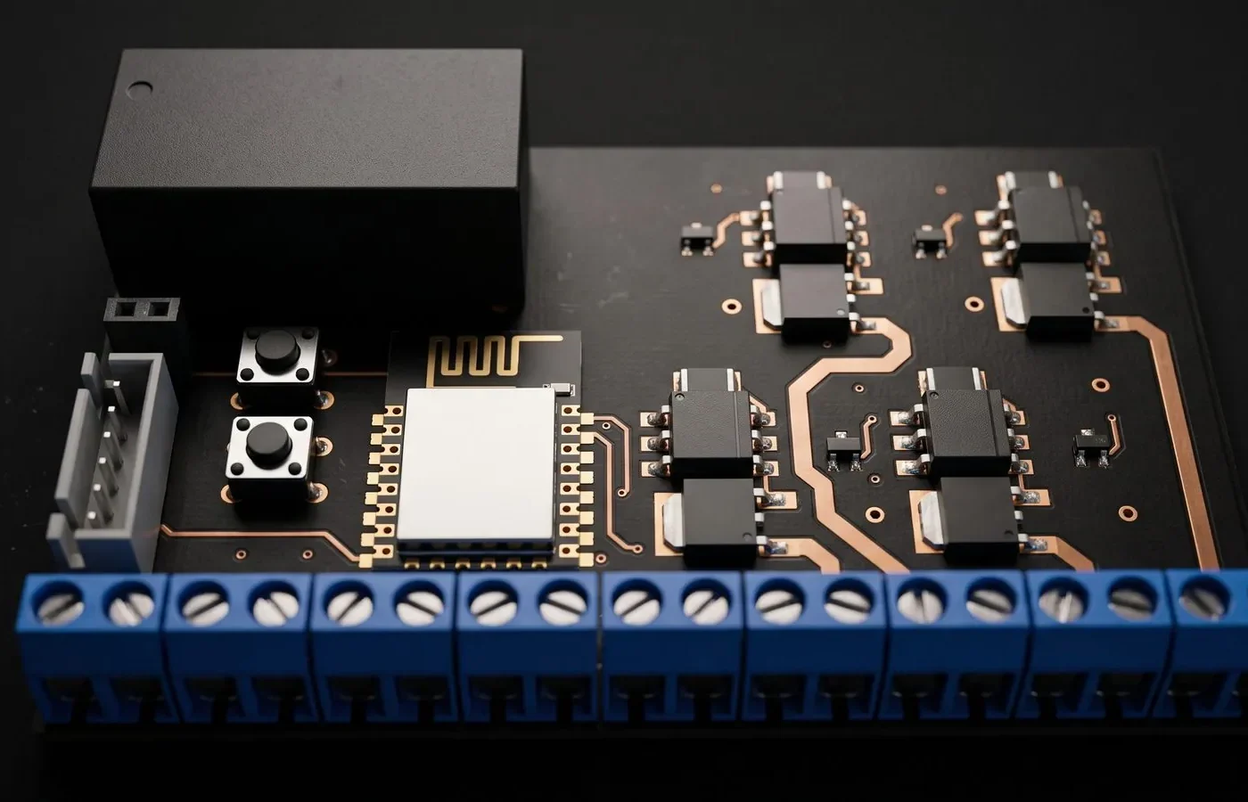
A mains-powered smart controller that switches eight AC loads and reads eight digital inputs over Wi-Fi. It is built around an ESP-12E (ESP8266) module, and the mains side is optically isolated from the logic side.
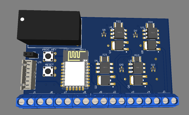
- Wi-Fi controller: The ESP-12E module drives eight output channels and reads eight inputs. A 6-pin serial programming header, RESET button and PROG (boot) button make flashing simple.
- Direct mains power: An HLK-PM01 AC-DC module generates 5 V from mains, and an AMS1117-3.3 regulator supplies the 3.3 V logic rail.
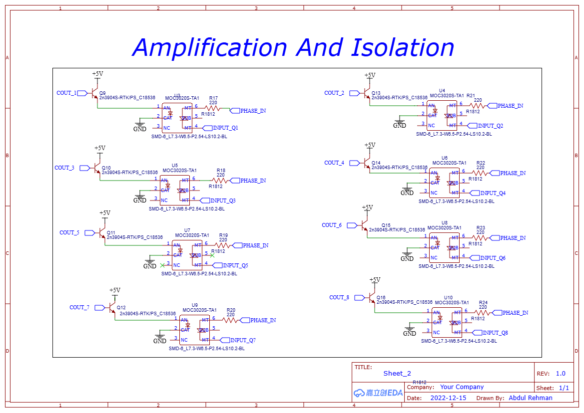
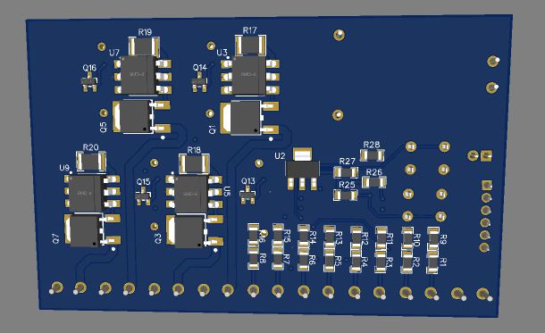
- Eight isolated AC outputs: Each channel uses a 2N3904 transistor driver, a MOC3020 optocoupler triac driver and a BT136S-800DJ 800 V triac. The microcontroller never touches mains voltage.
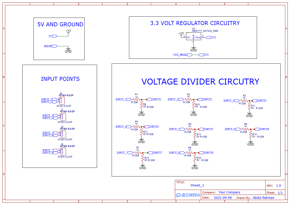
- Eight protected inputs: Each input has a 1 kΩ / 2 kΩ resistor divider that scales a 5 V signal down to a safe 3.3 V for the ESP8266. Inputs are wired to screw terminals.
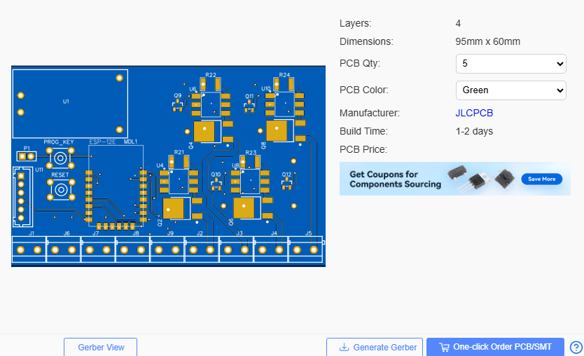
- Screw terminal connections: Four 2-pin terminals carry the eight switched outputs, plus separate terminals for the mains phase and neutral input.
- Clean layout by function: The schematic is organized into power-in, power-out, isolation, input and controller sections.
Design details
Design summary
| CAD tool | EasyEDA |
|---|---|
| Overview | A mains-powered smart controller that switches eight AC loads and reads eight digital inputs over Wi-Fi. |
| Wi-Fi controller | The ESP-12E module drives eight output channels and reads eight inputs. |
| Direct mains power | An HLK-PM01 AC-DC module generates 5 V from mains, and an AMS1117-3.3 regulator supplies the… |
| Eight isolated AC outputs | Each channel uses a 2N3904 transistor driver, a MOC3020 optocoupler triac driver and a… |
| Eight protected inputs | Each input has a 1 kΩ / 2 kΩ resistor divider that scales a 5 V signal down to a safe 3.3 V… |
| Screw terminal connections | Four 2-pin terminals carry the eight switched outputs, plus separate terminals for the mains… |
| Clean layout by function | The schematic is organized into power-in, power-out, isolation, input and controller sections. |
Have a board like this?
Send us the schematic, the mechanical constraints and the deadline. We will tell you what it takes and what it costs.