
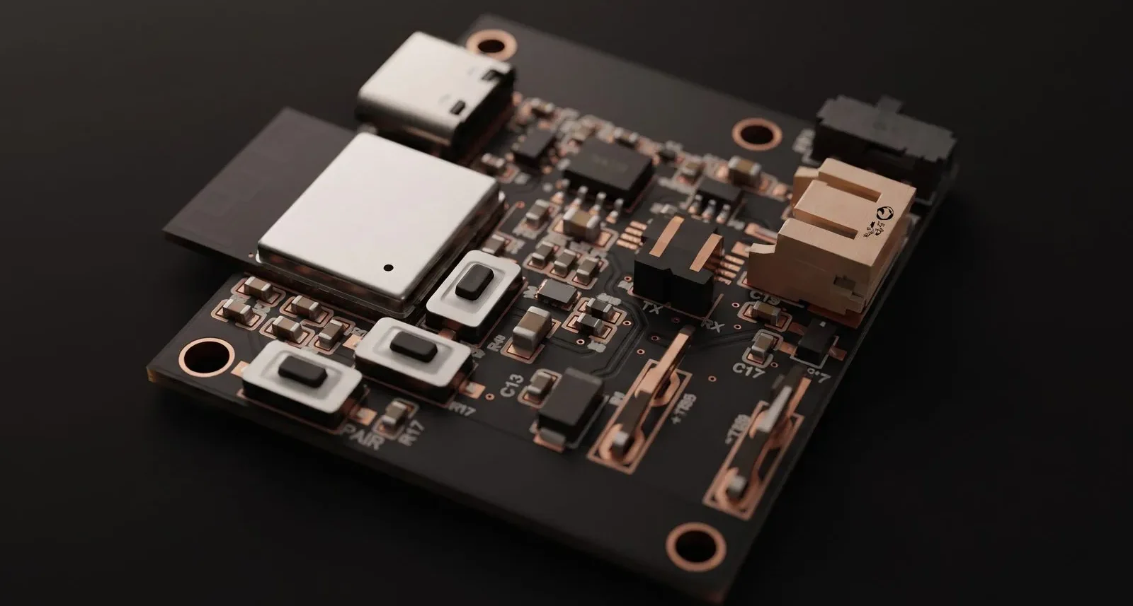
ESP32-C3 Battery Voltage Node
Self-powered ESP32-C3 node reading cell voltage through a 16-bit ADS1115.
The brief
A battery node that has to survive being outdoors: measure its own supply reliably, charge from USB, and report over serial, all from one lithium cell.
The measurement is the interesting part. The ESP32-C3’s own ADC is inconvenient for this, so an external 16-bit ADS1115 reads a scaled sense line instead — which buys the accuracy needed to tell a healthy cell from a failing one.
What we did
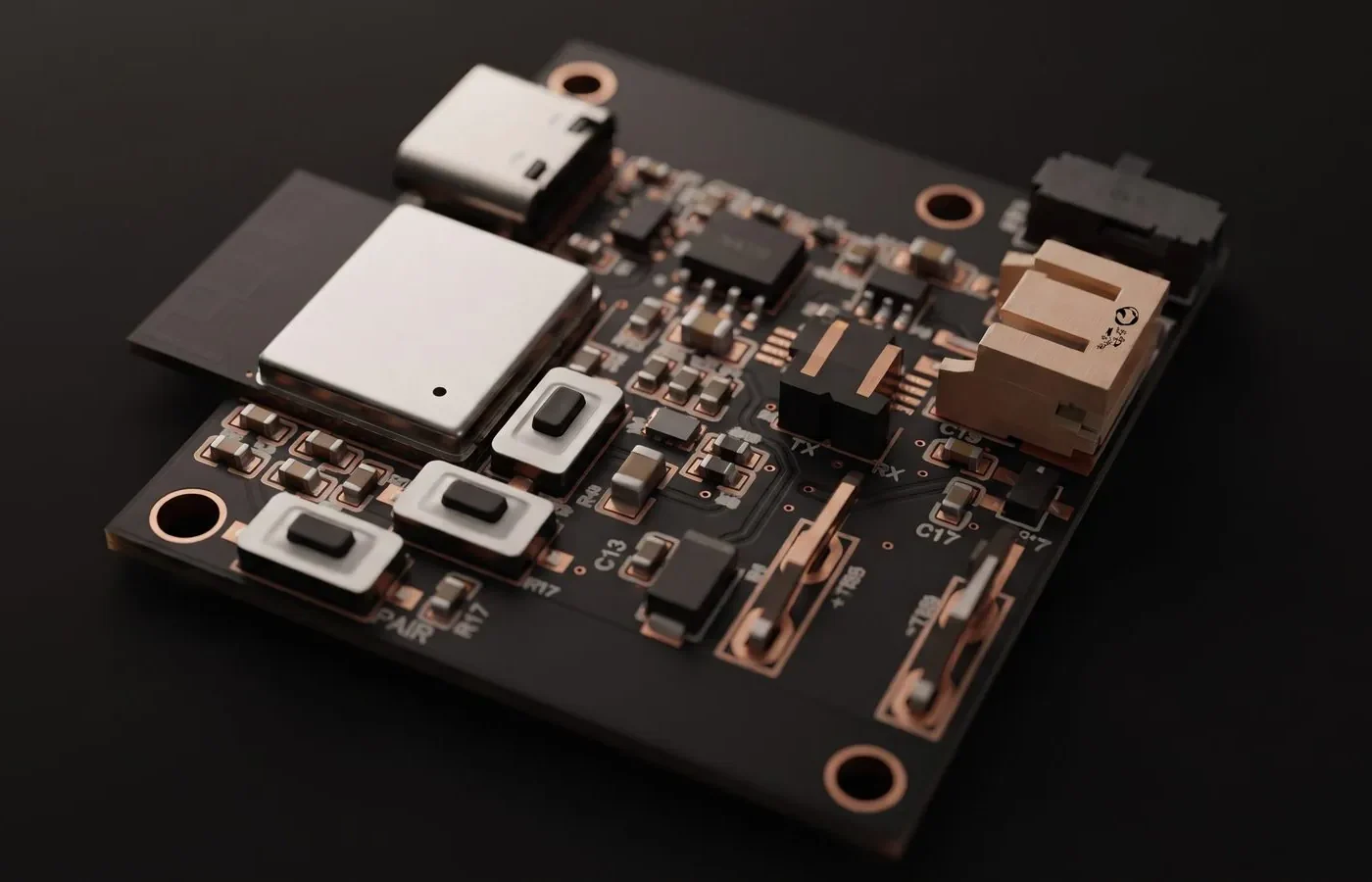
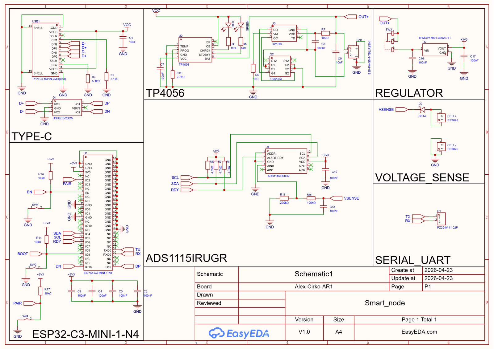
A battery-powered sensing node built around the ESP32-C3-MINI-1. It measures its own cell voltage on an external 16-bit ADC, charges over USB-C, and reports over USB or a serial header.
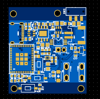
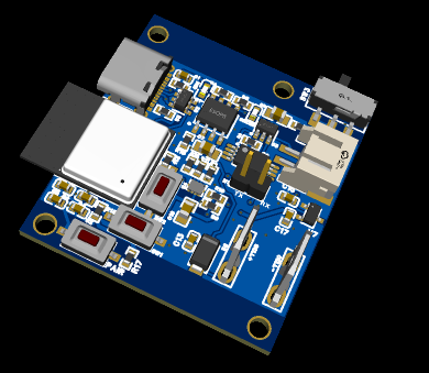
- Main controller: The ESP32-C3-MINI-1 module carries the logic and connectivity, with an EN reset button on a 10 kΩ pull-up, a BOOT button for flashing and a PAIR button. Four 100 nF decoupling capacitors sit on the 3.3 V rail.
- USB-C: A USB-C connector with 5.1 kΩ CC resistors so the board identifies as a power sink, and an USBLC6-2SC6 giving ESD protection on D+ and D−. VBUS becomes the VCC rail.
- Li-ion charging and protection: A TP4056 charging circuit with red and green status LEDs, paired with a DW01A protection IC and an FS8205A dual MOSFET for over-charge, over-discharge and over-current protection. The cell connects on a JST S2B-PH header and the protected output is labelled OUT+.
- Regulation: A TPMCP1700T-3302E/TT steps the battery rail down to a stable 3.3 V for the ESP32-C3 and the ADC, with a power switch on the OUT+ line.
- Voltage sensing: An SS14 Schottky diode and the CELL+/CELL− connectors feed a 220 kΩ / 100 kΩ divider with a 100 nF filter capacitor into the ADC’s AIN0 input — scaling roughly 4.2 V down to about 1.3 V.
- ADC: A 16-bit ADS1115 on I²C with 4.7 kΩ pull-ups on SCL, SDA and the ALERT/RDY line, its address pin tied to ground and its own 100 nF decoupling.
- Serial UART: A two-pin header exposing TX and RX for debugging or for connecting another device.
Design details
Design summary
| Overview | A battery-powered sensing node built around the ESP32-C3-MINI-1. |
|---|---|
| Main controller | The ESP32-C3-MINI-1 module carries the logic and connectivity, with an EN reset button on a 10… |
| USB-C | A USB-C connector with 5.1 kΩ CC resistors so the board identifies as a power sink, and… |
| Li-ion charging and protection | A TP4056 charging circuit with red and green status LEDs, paired with a DW01A protection IC… |
| Regulation | A TPMCP1700T-3302E/TT steps the battery rail down to a stable 3.3 V for the ESP32-C3 and the… |
| Voltage sensing | An SS14 Schottky diode and the CELL+/CELL− connectors feed a 220 kΩ / 100… |
| ADC | A 16-bit ADS1115 on I²C with 4.7 kΩ pull-ups on SCL, SDA and the ALERT/RDY line, its… |
| Serial UART | A two-pin header exposing TX and RX for debugging or for connecting another device. |
Have a board like this?
Send us the schematic, the mechanical constraints and the deadline. We will tell you what it takes and what it costs.