

LC RF Filter Circuit
Inductor-capacitor filter for RF signals, ordered through PCBWay.
The brief
A passive LC network has no active components to stabilise it, so its response is decided almost entirely by layout. At these frequencies the trace itself has inductance and capacitance, and the difference between a working filter and a mystery is measured in millimetres.
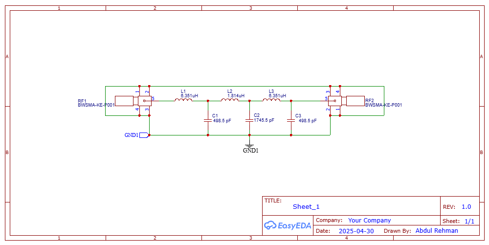
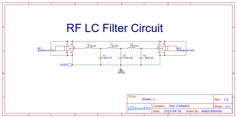
Six elements in a ladder gives a low-pass response, and 50 Ω SMA connectors on both ends let the network be dropped into a test chain and measured rather than trusted.
What we did
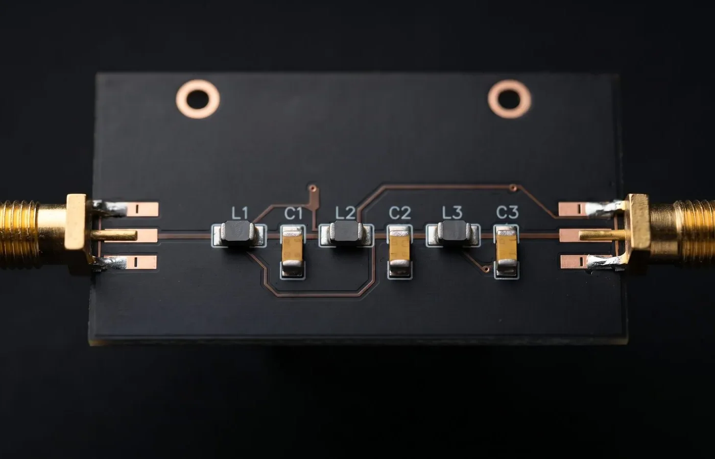
A compact 50 Ω passive LC filter board with SMA connectors at both ends, made for RF test setups and signal chains. It is a six-element ladder network with series inductors and shunt capacitors, which gives a low-pass response.
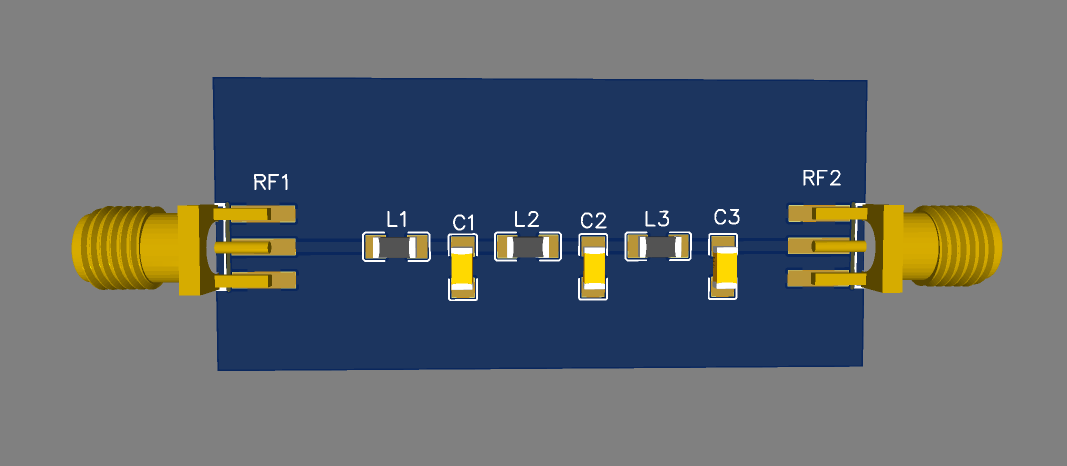
- Ladder filter network: Three series inductors (6.351 µH, 1.814 µH, 6.351 µH) alternate with three shunt capacitors (498.5 pF, 1745.5 pF, 498.5 pF). The values are symmetrical, which suggests a calculated filter response rather than trial and error.
- SMA connectors: An edge-mount SMA jack at each end, so the board can be dropped straight into a 50 Ω test setup.
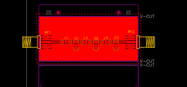
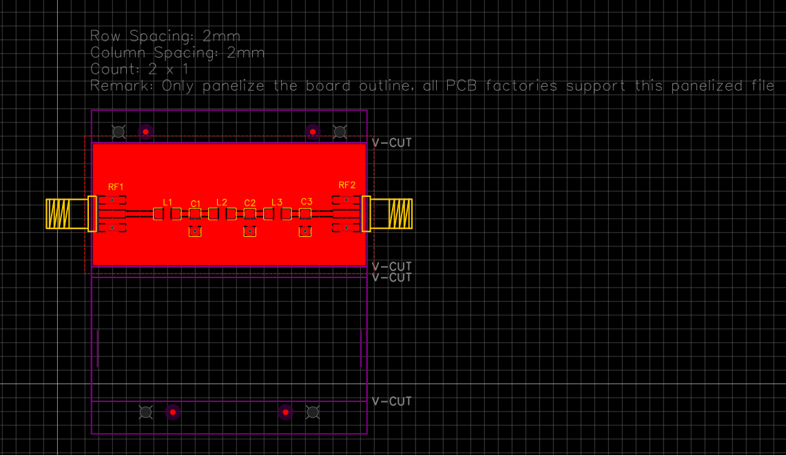
- RF-oriented layout: The signal path is a straight line from input to output, with short traces and the components placed in order along it. A continuous ground plane runs under and around the signal path, with the shunt capacitors tied directly to it.
- Manufacturing ready: The board is set up as a V-cut panel for fabrication, with tooling holes and fiducial-style marks.
Design details
Design summary
| CAD tool | EasyEDA |
|---|---|
| Overview | A compact 50 Ω passive LC filter board with SMA connectors at both ends, made for RF test setups and signal chains. |
| Ladder filter network | Three series inductors (6.351 µH, 1.814 µH, 6.351 µH) alternate with three shunt capacitors… |
| SMA connectors | An edge-mount SMA jack at each end, so the board can be dropped straight into a 50 Ω test… |
| RF-oriented layout | The signal path is a straight line from input to output, with short traces and the components… |
| Manufacturing ready | The board is set up as a V-cut panel for fabrication, with tooling holes and fiducial-style… |
Have a board like this?
Send us the schematic, the mechanical constraints and the deadline. We will tell you what it takes and what it costs.