

C1101 RF Receiver Board
ASK demodulating receiver on a C1101 RF module, assembled at JLCPCB.
The brief
This board has to receive a command over a radio link and then act on it by switching a genuinely heavy load. The radio and the PWM generation sit on an Arduino; everything that touches power sits on discrete 650 V MOSFETs. That split is the design.
The layout task follows from it — keeping a 650 V switching stage and a sensitive radio receiver on the same board without the first behaving like an antenna for the second.

What we did
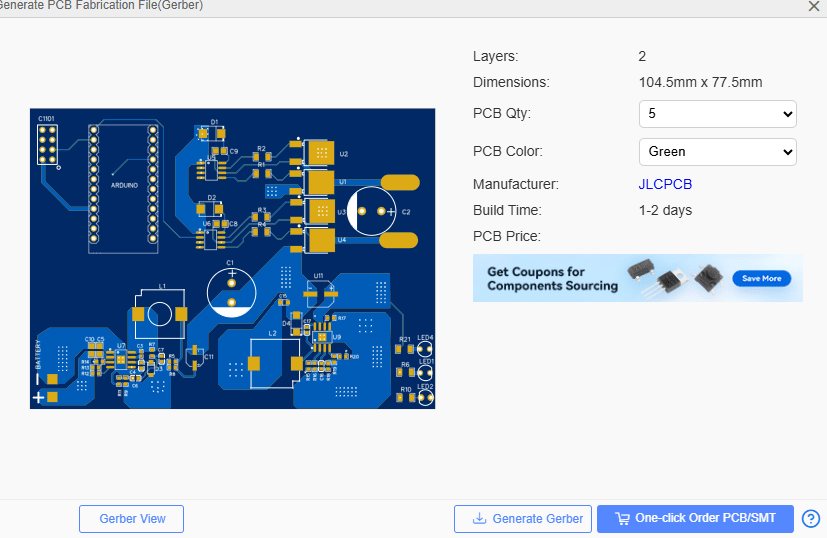
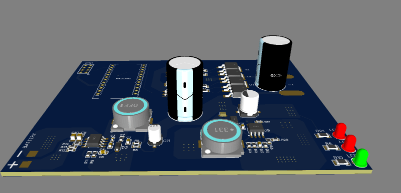
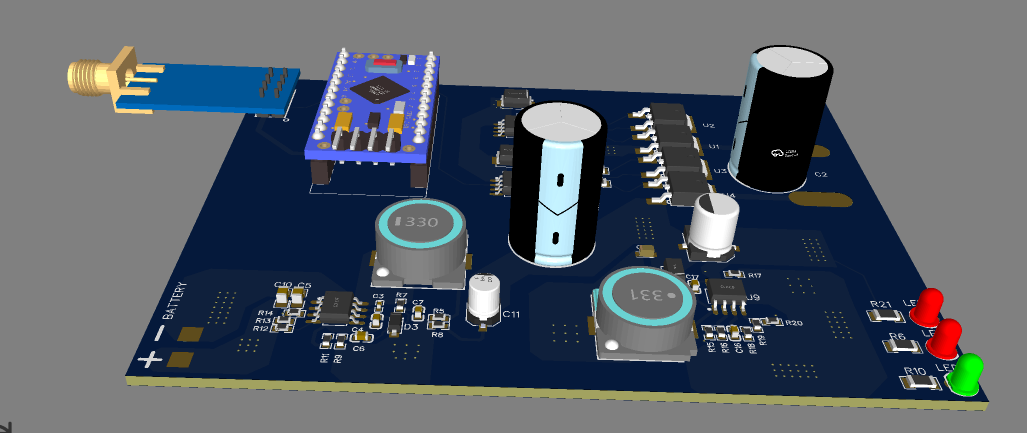
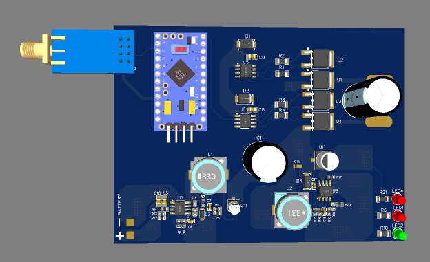
A battery-powered receiver board that listens for commands over a sub-GHz radio link and drives a high-power load through a full H-bridge. An Arduino handles the radio and generates the PWM drive signals, and the power stage is built from discrete 650 V MOSFETs, so the board handles much more power than a typical hobby driver.
- Wireless link: A CC1101 sub-GHz RF transceiver with an SMA antenna connector receives commands, giving a long range link that doesn’t depend on Wi-Fi or Bluetooth.
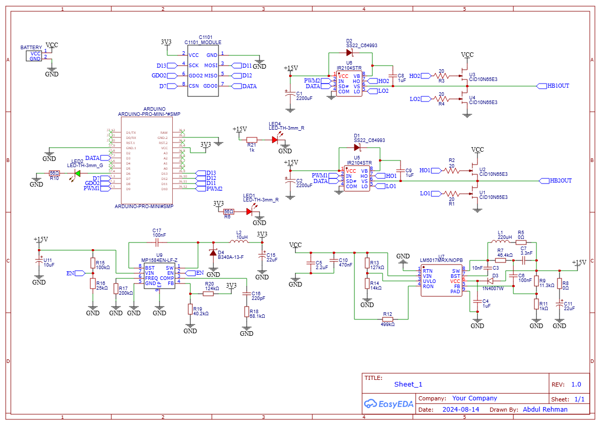
- Controller: An Arduino Pro Mini reads the radio over SPI and creates the PWM and data signals for the bridge. It has a programming header and status LEDs.
- Full H-bridge power stage: Two half-bridges, each built from two CID10N65E3 650 V MOSFETs driven by an IR2104 half-bridge gate driver. Each driver has a bootstrap diode and capacitor, and every gate has a 20 Ω series resistor for controlled switching. The two outputs (HB1OUT and HB2OUT) drive the load in both directions.
- Multi-stage power supply: The battery feeds an LM5017 wide-input buck regulator that makes the 15 V gate-drive rail, and an MP1584 buck converter makes the 3.3 V logic rail from it. Large 2200 µF bulk capacitors support the bridge’s current surges.
- Status indicators: Red and green LEDs show power and radio or data activity.
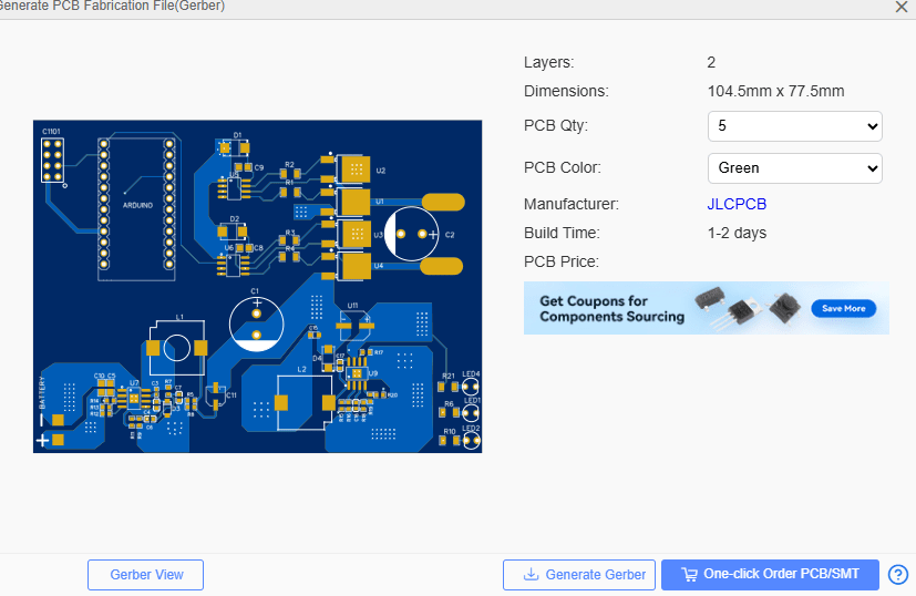
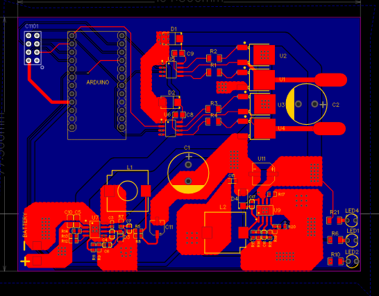
- Layout: A two-layer design with large copper pours and wide traces for the high-current paths, and the power stage, regulators and radio kept in separate zones. Large inductors and electrolytic capacitors are placed close to their converters.
Design details
Design summary
| CAD tool | EasyEDA |
|---|---|
| Overview | A battery-powered receiver board that listens for commands over a sub-GHz radio link and drives a high-power load through a full H-bridge. |
| Wireless link | A CC1101 sub-GHz RF transceiver with an SMA antenna connector receives commands, giving a long… |
| Controller | An Arduino Pro Mini reads the radio over SPI and creates the PWM and data signals for the… |
| Full H-bridge power stage | Two half-bridges, each built from two CID10N65E3 650 V MOSFETs driven by an IR2104 half-bridge… |
| Multi-stage power supply | The battery feeds an LM5017 wide-input buck regulator that makes the 15 V gate-drive rail, and… |
| Status indicators | Red and green LEDs show power and radio or data activity. |
| Layout | A two-layer design with large copper pours and wide traces for the high-current paths, and the… |
Have a board like this?
Send us the schematic, the mechanical constraints and the deadline. We will tell you what it takes and what it costs.