

Wireless RCP Radio Interface
STM32H523 prototype bridging a wired RS-422 link to a 2.4 GHz radio.
The brief
A wireless link is only useful if the thing it replaces still works, so this board bridges a wired RS-422 connection to a 2.4 GHz radio instead of replacing either. Both ends of that bridge have different noise and power expectations.
RS-422 in particular is specified for long runs and noisy environments, which is why the interface is treated as a real differential connection rather than two single-ended wires.
What we did
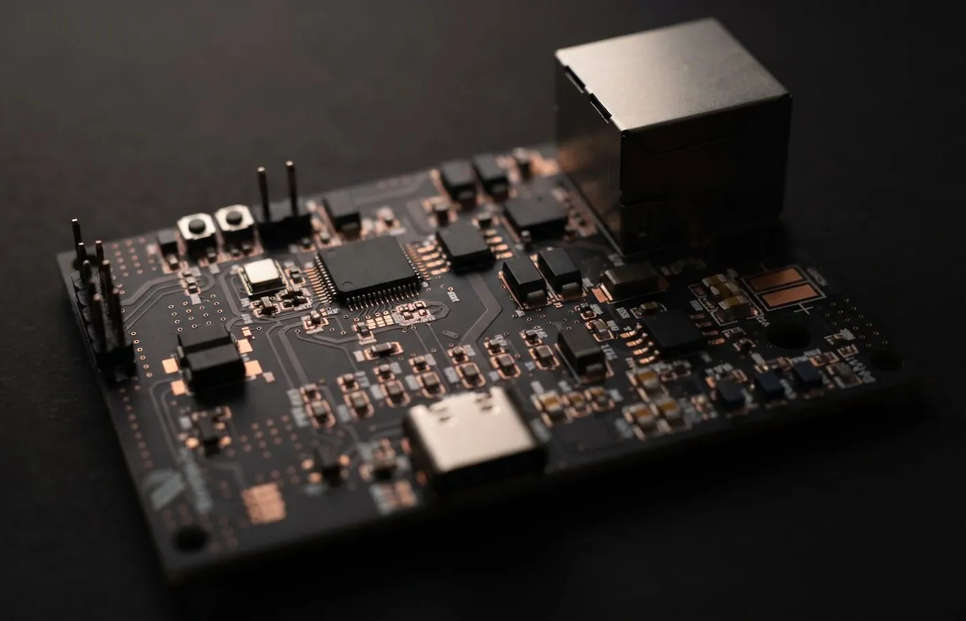
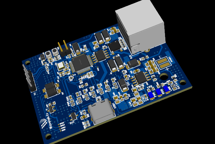
A prototype wireless control board built around an STM32H523 microcontroller and a 2.4 GHz radio module. It bridges a wired RS-422 link to the radio, with status indicators, flexible power input and USB-C programming.
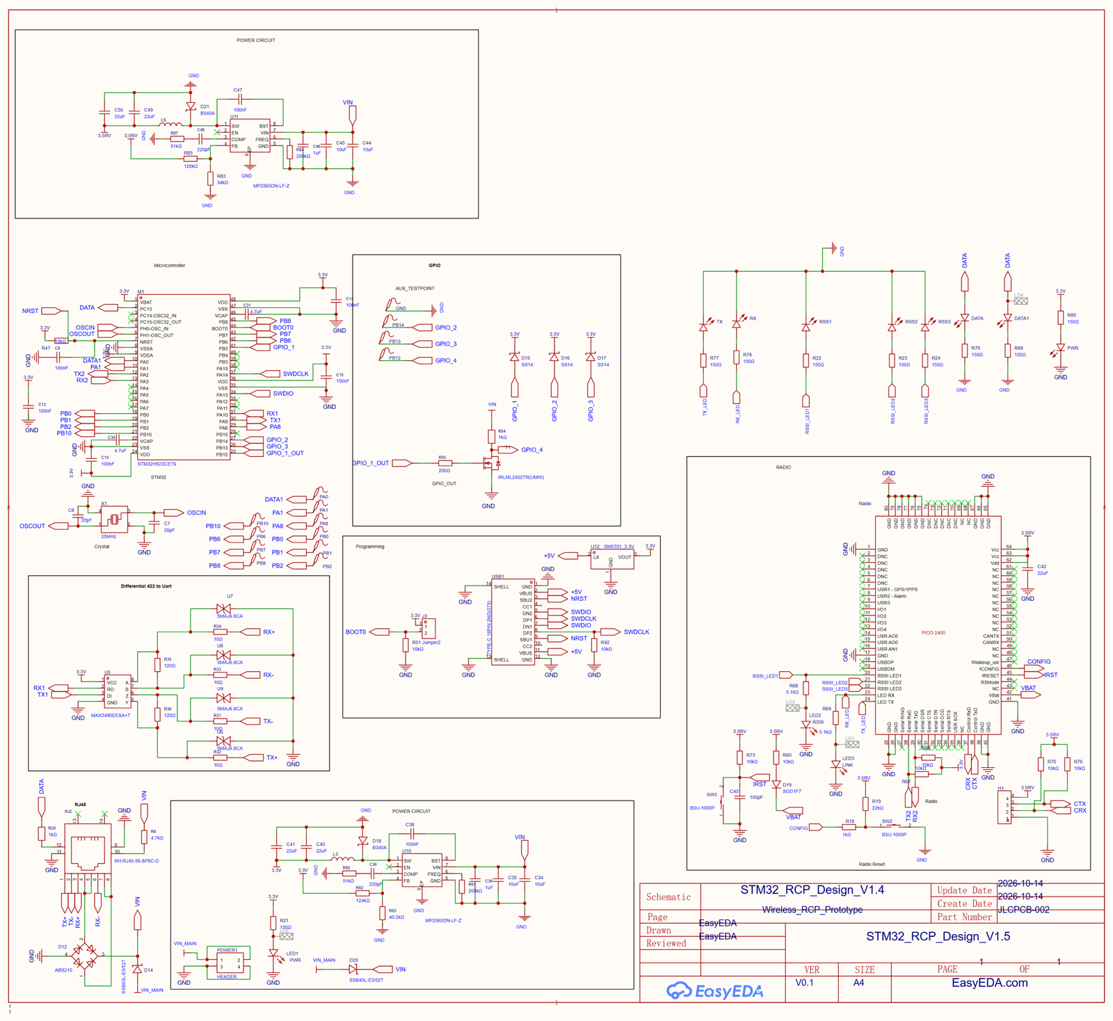
- Main controller: An STM32H523CET6 with a 25 MHz crystal, and breakouts for UART, GPIO and SWD debug lines.
- Wireless radio: A 2.4 GHz radio module connected over serial, with RSSI signal-strength LEDs, link, TX and RX activity LEDs, a config button and a reset button.
- RS-422 interface: A MAX3490 transceiver converts the MCU’s UART to differential RS-422 for long, noise-resistant cable runs, with 120 Ω termination and SMAJ6.8CA TVS diodes for surge protection.
- RJ45 connector: One connector carries the differential data lines and power.
- Robust power input: A bridge rectifier and Schottky diodes accept either polarity on the input, then two MP2565 buck converters step it down to a 3.5 V radio rail and a 3.3 V logic rail. A power-select header and a PWR LED are included.
- Programming and debug: A USB-C connector exposes SWD (SWDIO, SWDCLK, NRST) and 5 V, with a 3.3 V regulator and a BOOT0 jumper for firmware loading.
- GPIO and I/O: Test points, status LEDs and a MOSFET-driven output for controlling external loads.
Design details
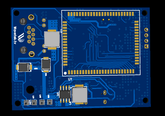
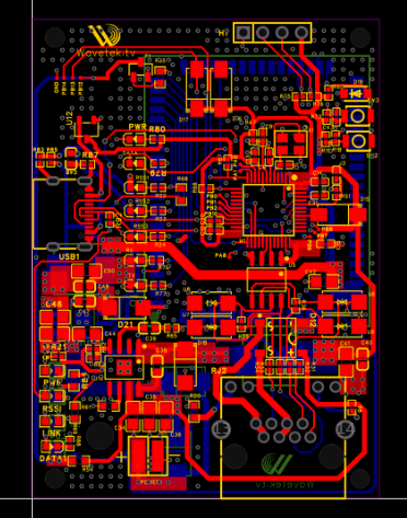
Design summary
| CAD tool | EasyEDA |
|---|---|
| Overview | A prototype wireless control board built around an STM32H523 microcontroller and a 2.4 GHz radio module. |
| Main controller | An STM32H523CET6 with a 25 MHz crystal, and breakouts for UART, GPIO and SWD debug lines. |
| Wireless radio | A 2.4 GHz radio module connected over serial, with RSSI signal-strength LEDs, link, TX and RX… |
| RS-422 interface | A MAX3490 transceiver converts the MCU’s UART to differential RS-422 for long, noise-resistant… |
| RJ45 connector | One connector carries the differential data lines and power. |
| Robust power input | A bridge rectifier and Schottky diodes accept either polarity on the input, then two MP2565… |
| Programming and debug | A USB-C connector exposes SWD (SWDIO, SWDCLK, NRST) and 5 V, with a 3.3 V regulator and a… |
| GPIO and I/O | Test points, status LEDs and a MOSFET-driven output for controlling external loads. |
Have a board like this?
Send us the schematic, the mechanical constraints and the deadline. We will tell you what it takes and what it costs.