
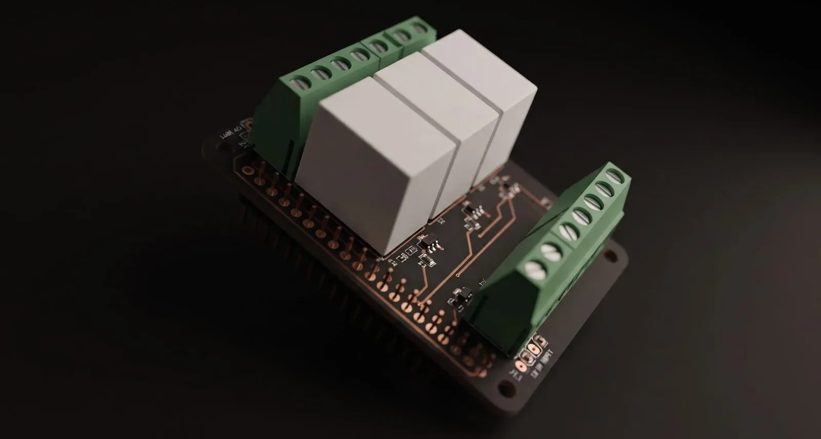
Raspberry Pi Relay & Sensor HAT
HAT with three 12 V relay outputs, I2C sensor ports and a pass-through header.
The brief
A Raspberry Pi cannot switch a 12 V load. Its GPIO pins are 3.3 V, limited to a few tens of milliamps, and they are not isolated from the Pi’s ground — so wiring a relay straight to them is wrong on three counts at once.
The board solves that with transistor-driven relays, while staying inside the HAT form factor so the GPIO header can still be used to stack something else on top.
What we did
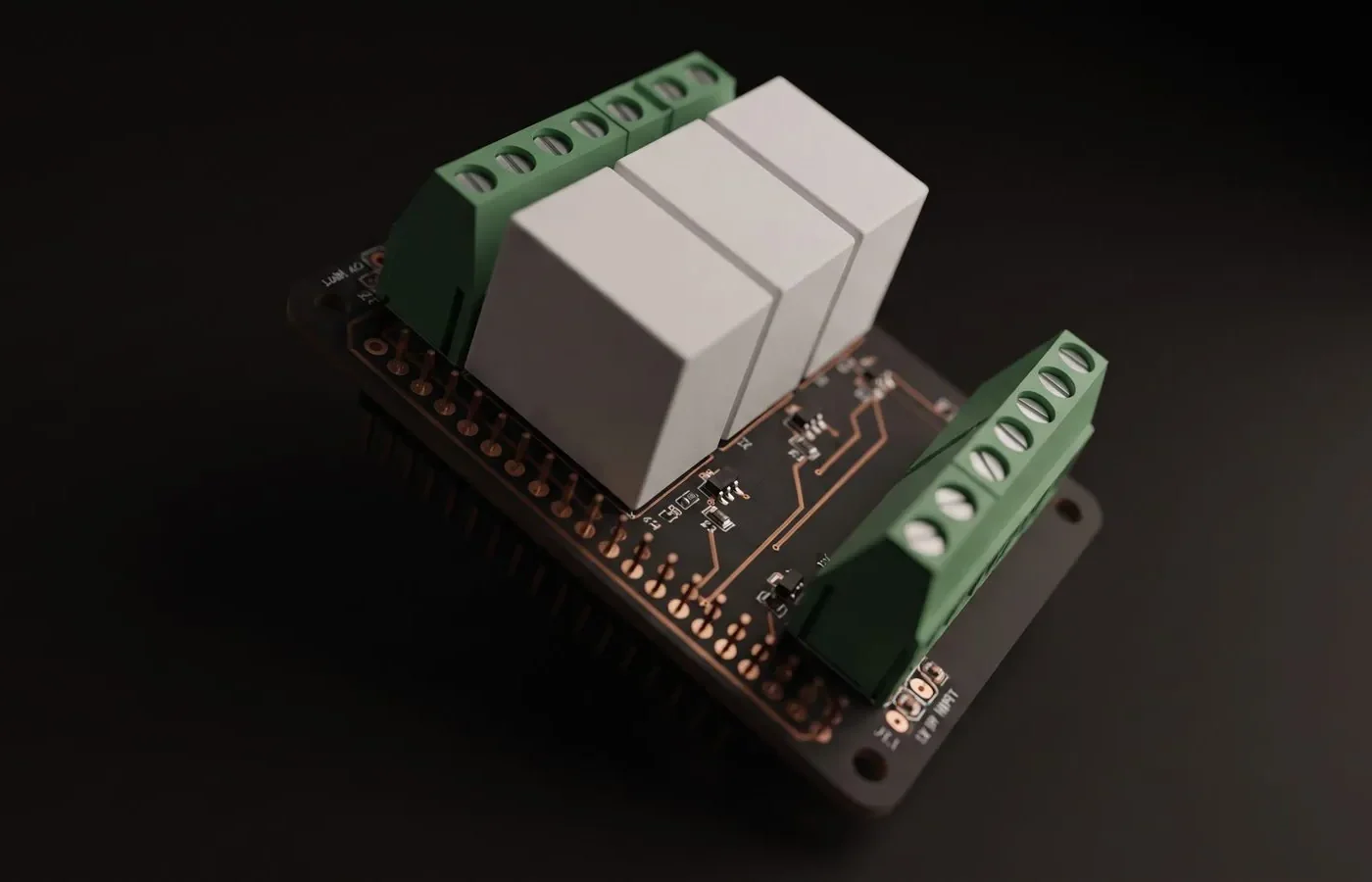
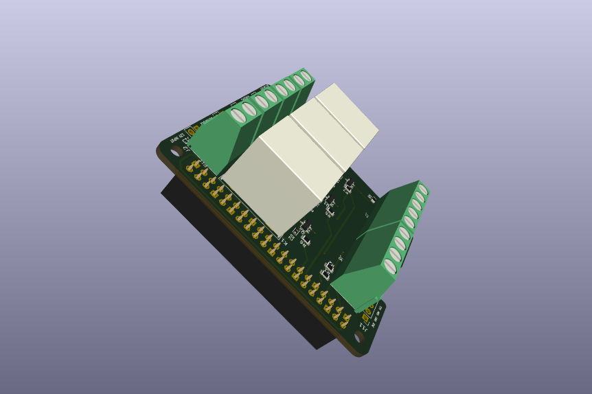
A Raspberry Pi add-on board (HAT) that lets the Pi switch 12 V loads and connect external sensors. It plugs onto the Pi’s 40-pin GPIO header and takes 12 V from an external supply.
- Raspberry Pi HAT form factor: A 40-pin GPIO connection to the Pi, plus a pass-through 2×20 header so other boards can still be stacked on top.
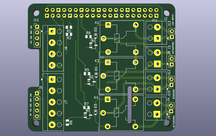
- Relay outputs: Three JQC-3FF 5 V relays, each driven from a Pi GPIO line through an SS8050 transistor, with a 1N4148W flyback diode to protect against voltage spikes. Each relay’s common and normally-open contacts go to screw terminals, and the board supplies 12 V to the switched circuit.
- I2C sensor ports: Dedicated 4-pin connectors carry 3.3 V, GND, SDA and SCL to external I2C sensors, with 4.7 kΩ pull-ups on the bus.
- Analog and signal sensor input: Additional connectors take a sensor signal line, with a series resistor to protect the Pi’s input.
- Power distribution: The 3.3 V, 5 V, GND and 12 V rails are all broken out, with power flags in the schematic for clean ERC.
Design details
Design summary
| CAD tool | KiCad |
|---|---|
| Overview | A Raspberry Pi add-on board (HAT) that lets the Pi switch 12 V loads and connect external sensors. |
| Raspberry Pi HAT form factor | A 40-pin GPIO connection to the Pi, plus a pass-through 2x20 header so other boards can still… |
| Relay outputs | Three JQC-3FF 5 V relays, each driven from a Pi GPIO line through an SS8050 transistor, with a… |
| I2C sensor ports | Dedicated 4-pin connectors carry 3.3 V, GND, SDA and SCL to external I2C sensors, with 4.7 kΩ… |
| Analog and signal sensor input | Additional connectors take a sensor signal line, with a series resistor to protect the Pi’s… |
| Power distribution | The 3.3 V, 5 V, GND and 12 V rails are all broken out, with power flags in the schematic for… |
Have a board like this?
Send us the schematic, the mechanical constraints and the deadline. We will tell you what it takes and what it costs.