

UWB Transceiver
Complete UWB transmitter and receiver, ordered with assembly from JLCPCB.
The brief
UWB is used for ranging, so the radio has to be able to hear a very weak return from a distant tag. Pairing that with an ESP8266 on the same board means the noisy digital section is a threat to the measurement it exists to make.
A compact board with USB programming and status indication was the practical answer: everything the module needs, on one surface, with the layout treating the RF section as the sensitive part.
What we did
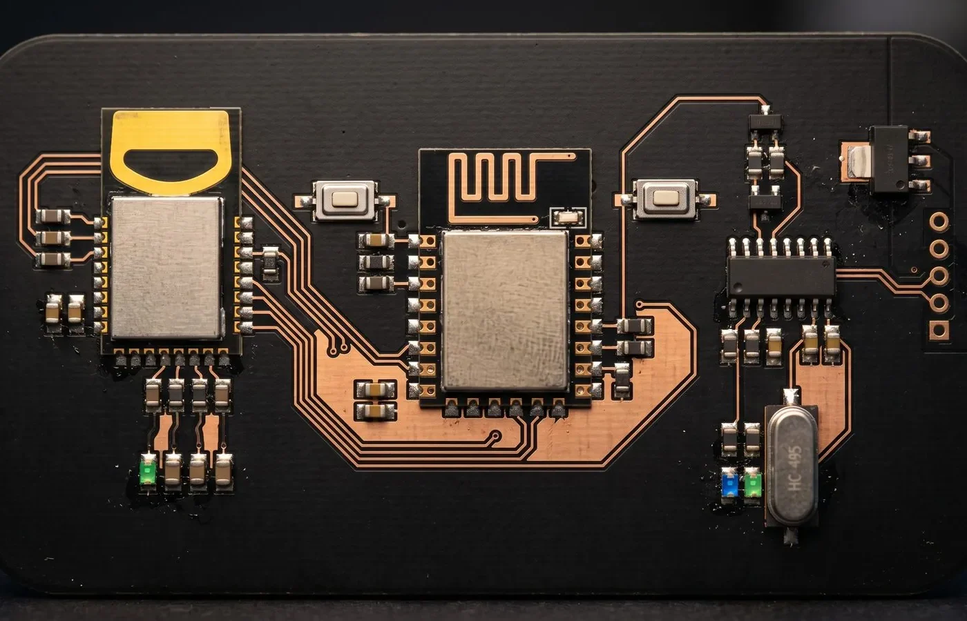
A compact wireless board that combines an ESP-12E (ESP8266) microcontroller with a 3.5 GHz ultra-wideband (UWB) radio module. UWB gives precise distance measurement, which suits indoor positioning, asset tracking and ranging projects. The board has USB programming and status indicators built in.
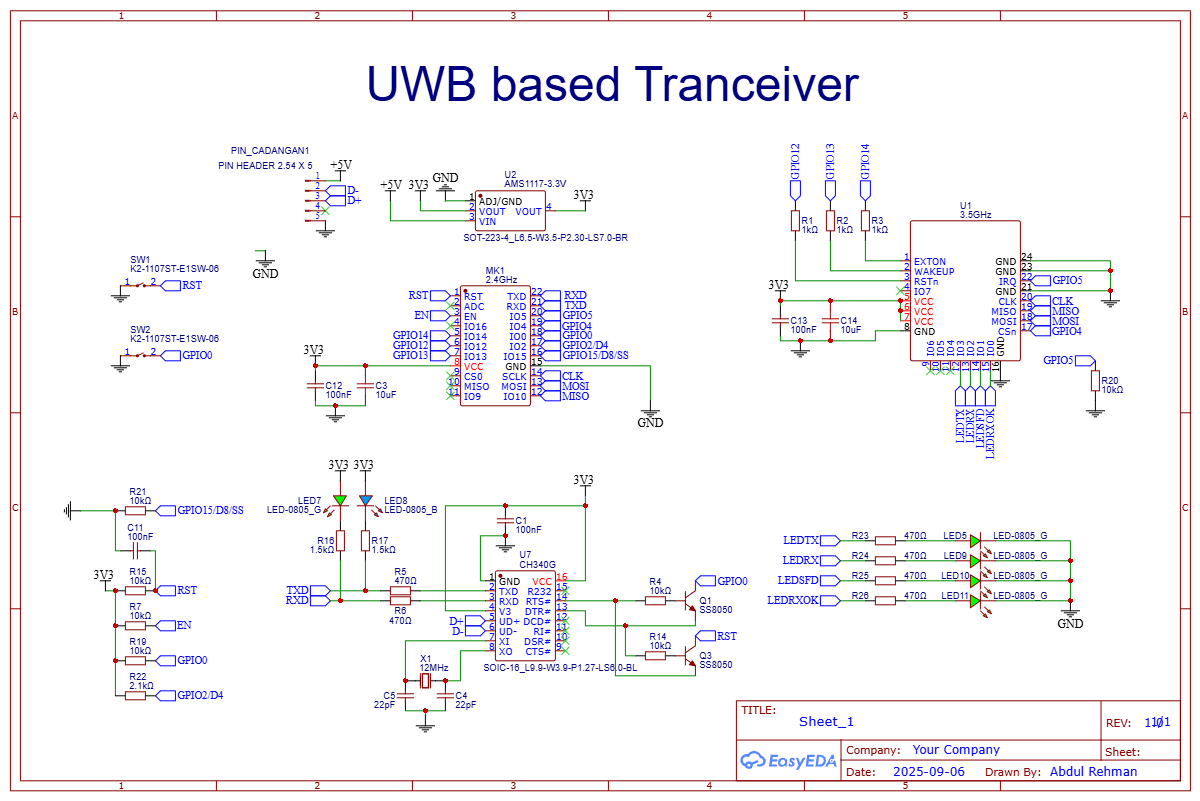
- UWB radio: A 3.5 GHz UWB module connects to the ESP-12E over SPI, with interrupt, wake-up and reset lines. 1 kΩ resistors on the control pins set safe default states.
- Main controller: The ESP-12E handles the application logic and Wi-Fi, with RESET and BOOT (GPIO0) buttons and the pull-up and pull-down resistors needed for reliable boot.
- Onboard USB programming: A CH340G USB-to-UART chip with a 12 MHz crystal and two SS8050 transistors provides automatic reset and flash entry, so firmware can be uploaded without pressing buttons.
- Status LEDs: Four green LEDs on the UWB module’s activity lines (TX, RX, SFD and RX OK) show radio activity at a glance. Separate LEDs on the USB-UART lines show serial TX and RX traffic.
- Power: An AMS1117-3.3 regulator makes the 3.3 V rail from 5 V, with decoupling on every module.
- Expansion header: A 5-pin header brings out 5 V, USB data and ground for connecting power or a USB cable.
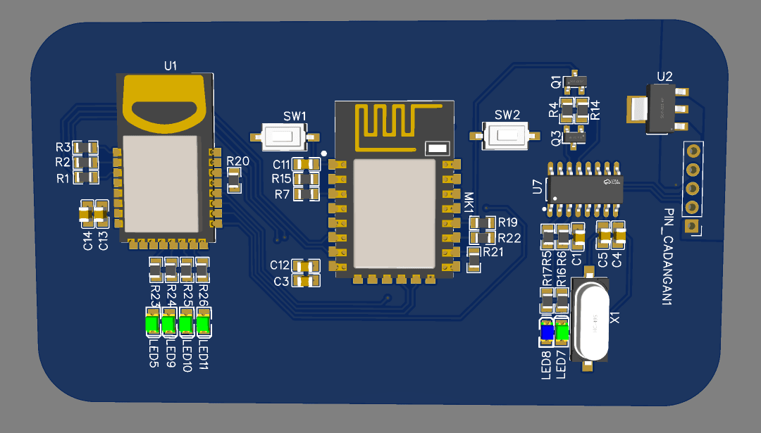
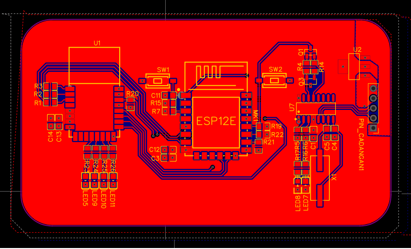
- Layout: A compact rounded-corner board with the UWB module on the left, the ESP-12E in the center and the USB and power section on the right, so noisy and sensitive sections stay apart. The board is mostly ground pour, with the antenna areas of both radio modules left clear of copper.
Design details
Design summary
| CAD tool | EasyEDA |
|---|---|
| Overview | A compact wireless board that combines an ESP-12E (ESP8266) microcontroller with a 3.5 GHz ultra-wideband (UWB) radio module. |
| UWB radio | A 3.5 GHz UWB module connects to the ESP-12E over SPI, with interrupt, wake-up and reset lines. |
| Main controller | The ESP-12E handles the application logic and Wi-Fi, with RESET and BOOT (GPIO0) buttons and… |
| Onboard USB programming | A CH340G USB-to-UART chip with a 12 MHz crystal and two SS8050 transistors provides automatic… |
| Status LEDs | Four green LEDs on the UWB module’s activity lines (TX, RX, SFD and RX OK) show radio activity… |
| Power | An AMS1117-3.3 regulator makes the 3.3 V rail from 5 V, with decoupling on every module. |
| Expansion header | A 5-pin header brings out 5 V, USB data and ground for connecting power or a USB cable. |
| Layout | A compact rounded-corner board with the UWB module on the left, the ESP-12E in the center and… |
Have a board like this?
Send us the schematic, the mechanical constraints and the deadline. We will tell you what it takes and what it costs.