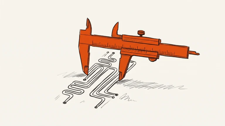
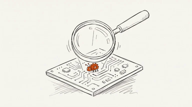
A correct RS-485 PCB design terminates the bus at both physical ends, biases the pair so an idle bus reads as a defined value, keeps the differential pair matched and free of stubs, and isolates the two ends of the link when they sit at different ground potentials. Miss one of those and the board works in the lab and fails in the field.
RS-485 is a serial bus standard that defines the electrical characteristics of a balanced interface, and it survives noisy multi-drop links consumer electronics rarely faces, which is why it is so widely used in industrial automation: metering, building management and remote I/O. Those characteristics decide your topology. They are set out in the RS-422 and RS-485 Standards Overview and System Configurations report from Texas Instruments: a maximum common-mode voltage of minus 7 to plus 12 volts, a driver differential output level of 2 volts or more and 10 volts or less for RS-485, a minimum driver load of 60 ohm, and a minimum receiver input resistance of 12 kohm.
Most engineers meet the bus through Modbus RTU, a protocol that specifies the frame and the timing, not the wire. The electrical layer underneath is RS-485, so termination, biasing and the common-mode budget are board decisions the protocol never mentions.
Termination and the reflections it absorbs
A bus is a transmission line. A driver output edge travelling along the pair meets a discontinuity, and where the load impedance does not match the characteristic impedance of the pair, energy reflects back down the wire. The receiver sees the arriving edge plus the echo of itself, and with an unterminated end that echo is a ringing edge large enough to flip a bit.
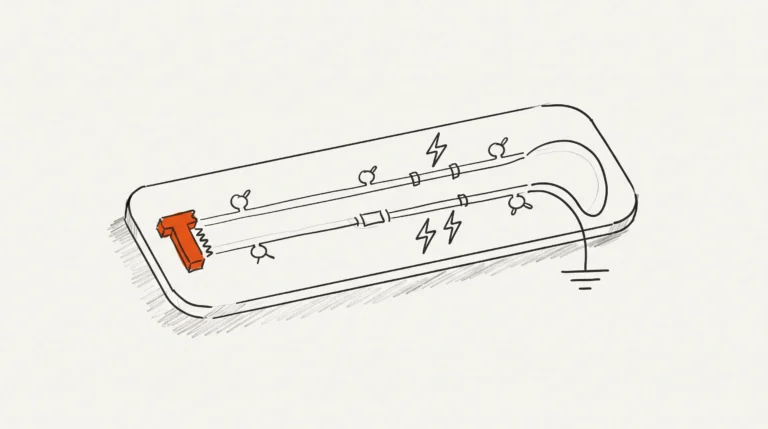
Termination is how you absorb that reflection. Fit a termination at each of the two physical ends of the bus, matched to the characteristic impedance of the twisted pair, and nowhere else. A termination in the middle of the run is a load that divides the signal and costs you margin. Placement matters as much as the schematic: a termination on a removable node is a termination that gets removed.
One number deserves care. The standards overview lists a minimum driver load of 60 ohm, which is tempting to read as a resistor value to fit, and it is not. Sixty ohm is the load the driver has to drive, and the receiver’s own figure, a minimum receiver input resistance of 12 kohm, bounds what the receiver draws. Neither is a termination value: that comes from the impedance of the cable you specified.
Texas Instruments’ The RS-485 Design Guide is a compendium for successful data transmission design and covers the important aspects of the RS-485 standard. We work through it when we check a board, and our PCB design review service is built around this list.
Fail-safe biasing: the bus with nobody talking
On a multi-drop bus most of the time no driver is enabled, so the pair is connected to the cable and the receivers and it floats. A floating differential pair is an antenna, and the receiver reads whatever the noise happened to be, which on a machine floor is not a state you can design around.
RS-485 is by nature of its balanced circuits and twisted-pair media, relatively immune to common-mode noise. However, conversion of common-mode noise to differential noise is possible in all real systems, due to unintended imbalances in the cabling and load.
Texas Instruments, Comparison of Differential-Mode Noise Immunity of RS-485 Receivers
Fail-safe biasing is what decides the idle state. A bias network holds the pair at a known differential voltage when no transmitter is active, so the bus reads as a defined value rather than noise. It appears as a pull-up and a pull-down on each leg, a fail-safe network inside the transceiver, or a bias at the bus end. The bias has to hold the whole bus without fighting a driver that is speaking.
The noise it holds the bus away from is worth naming. The report identifies switching power supplies, high-current machinery and radio-frequency coupling as the principal sources. So check the transceiver’s supply filtering, the return path of the noisy converter and the distance to the motor drive. Receiver hysteresis is also commonly used to ensure glitch-free reception in the presence of differential noise.
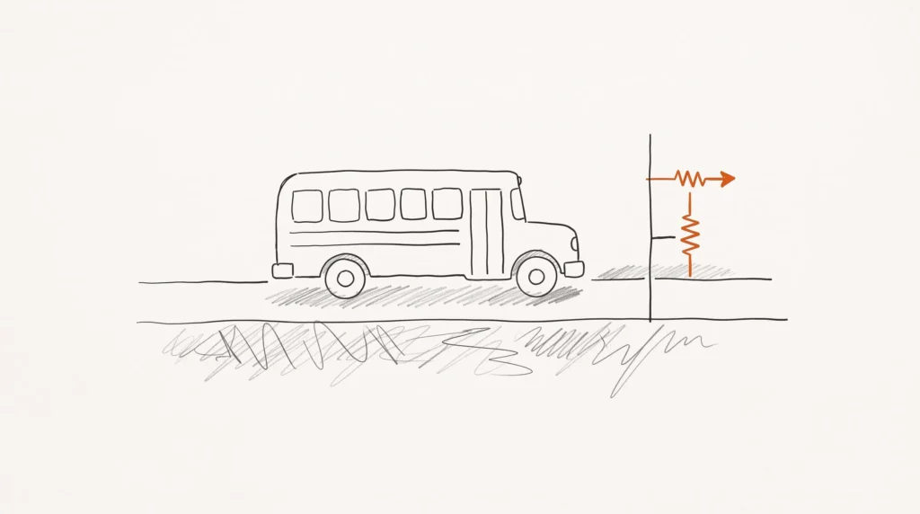
Most of the boards that reach us with this fault are industrial control boards, and the pattern is familiar: a working transceiver, a terminator the schematic called for, and a bus that reads noise when the machine is idle. Adding the bias is often a two-resistor change.
Common-mode range, ground offsets and isolation
The common-mode voltage is the pair voltage measured against the receiver’s local ground. It is the quiet part of the signal: both wires sit at the same potential. The standard gives it a window, a maximum common-mode voltage of minus 7 to plus 12 volts, and the receiver only works while it stays inside. Two devices at different ground potentials push it around, and outside that window the receiver clips or reads noise.
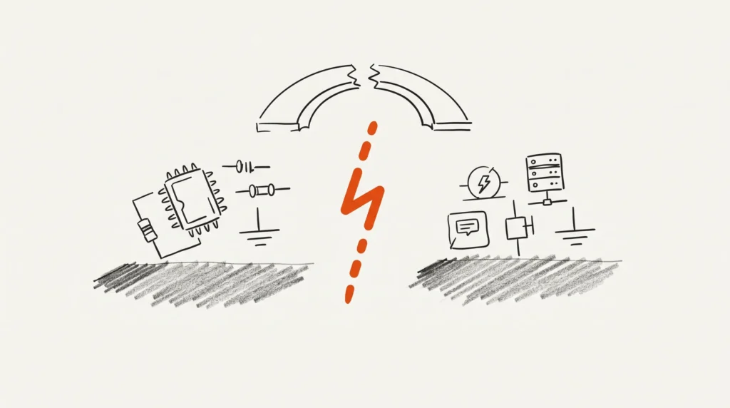
Ground potential difference is not exotic. It is the normal situation between two buildings, between a machine and a control cabinet, or between a plant floor and a substation. The fix is galvanic isolation: a barrier in the transceiver that breaks the DC path between the two sides, so each side of the bus is referenced to its own local ground. We wrote about the layout consequences on an isolated VE.direct HAT, where the barrier drove the ground plan.
Isolation changes the layout in three concrete ways. There is a second ground domain, so the board carries two ground planes that must not touch, joined only through components chosen to cross it. There is a real gap in the board, a keepout the copper pour, the drill and the assembly house all have to respect. And there is a defined boundary: the field side of it becomes a separate design.
A bus that has to live alongside ordinary network traffic is a different problem again. Our ESP32 Ethernet relay and KNX input board carries industrial buses next to everyday network traffic, where keeping the noisy converters away from the bus mattered as much as the termination.
Protection, and what each decision costs
The last piece is what sits between the transceiver pins and the connector. Surge and ESD protection belongs at the connector, not scattered across the board, chosen against the transceiver’s absolute maximum ratings and checked against the bus, because a part with too much capacitance or leakage degrades the signal it protects.
| Concern | What goes wrong without it | What to add | What it costs you |
|---|---|---|---|
| Termination | Reflections at the end of the run; ringing that flips a bit | A termination at each physical end, matched to the pair’s impedance | A resistor at each end, and the discipline that they stay there |
| Fail-safe biasing | An idle bus floats and the receiver reads the noise | A bias network holding the pair at a defined voltage | Two resistors, and a placement decision so it holds the bus |
| Common-mode range | The receiver is pushed outside the window the standard allows | A transceiver whose common-mode range covers your ground offset | Keeping the ground difference in range, or a wider-range part |
| Galvanic isolation | Ground differences between buildings drive the bus out of range | A galvanic isolation barrier between bus side and logic side | A second ground domain, a real gap in the board, and area |
| Surge and ESD protection | The transceiver pins take the hit, nothing between them and the wiring | Protection at the connector, selected against the transceiver’s ratings | Board area, and a check of the part’s capacitance and leakage |
| Cable and ground potential difference | The bench test is clean and the site installation is not | A reference conductor between the two ends | A conductor in the cable, and a grounding scheme with no second path |
Read the last row if the bus runs between buildings or a cabinet and a machine. The reference conductor keeps the common-mode voltage inside the receiver’s window. It is a reference, not a current return for the bus current, and it must not become a second earth path between grounds.
Frequently asked questions
Do I need termination resistors on RS-485?
Almost always yes, at the two physical ends of the bus, matched to the characteristic impedance of the twisted pair rather than a number from a reference design. The caveat is placement: a termination on a removable node is a termination that gets removed, and the failure appears as intermittent errors.
What is fail-safe biasing?
A network that biases the bus into a known state when no transmitter is driving it, so the receiver reads a defined value instead of noise. The noise is real: switching power supplies, high-current machinery and radio-frequency coupling are the main sources, and imbalances in the cabling and load convert common-mode noise into differential noise.
How far can I run an RS-485 cable?
There is no single number, and we will not invent one for you. The answer is a trade against data rate, set by the standard. The longer the cable and the higher the rate, the more the line loss and reflections eat into your margin. Past a certain point the signal at the far end is no longer cleanly resolvable, and the fix is a slower bus.
When do I need galvanic isolation on RS-485?
When the two ends of the link sit at different ground potentials, the normal case between two buildings or between a machine and a cabinet. The common-mode voltage at the receiver then includes that ground difference, and outside the window the standard allows, the receiver stops working properly. Isolation breaks the DC path between the sides. For layout that means a second ground domain, a real gap in the board that the pour, the drill and the assembly house must respect, and a defined boundary. It also means deciding how the isolated side gets its power.
Does RS-485 need a ground wire?
Yes, and the reason is precise. The differential pair alone carries the signal, but it leaves the common-mode voltage undefined, and the receiver needs a reference to interpret the difference against. A reference conductor between the two ends gives it that reference. It is a reference, not a current return for the bus current, and it must be connected so it does not become an unintended current path.
What to send us
Send the transceiver part number, the bus speed, the cable type and length, whether the two ends of the link sit at different ground potentials, and whether the design has to pass a regulatory isolation test. That is enough for us to say whether the topology holds and what must change.
If you want to see how an isolated bus has been laid out on a real board, the isolated VE.direct HAT is on the site, and the quote page is where this starts. We are rated 4.5 stars across 38 Fiverr reviews.