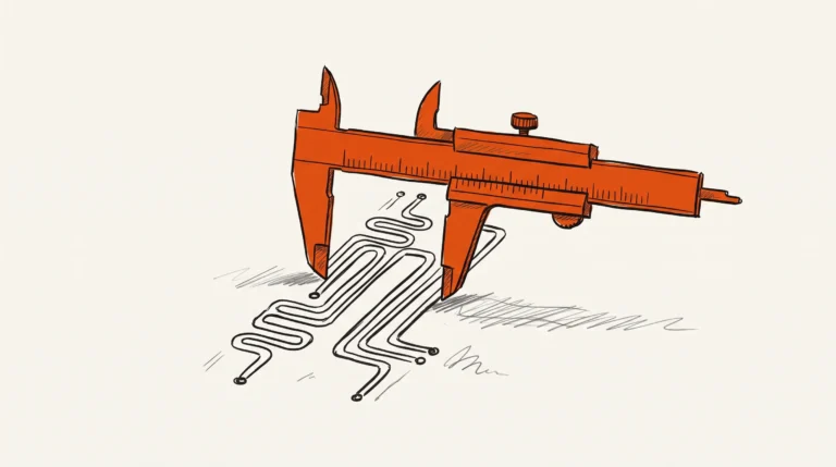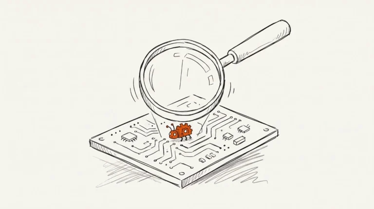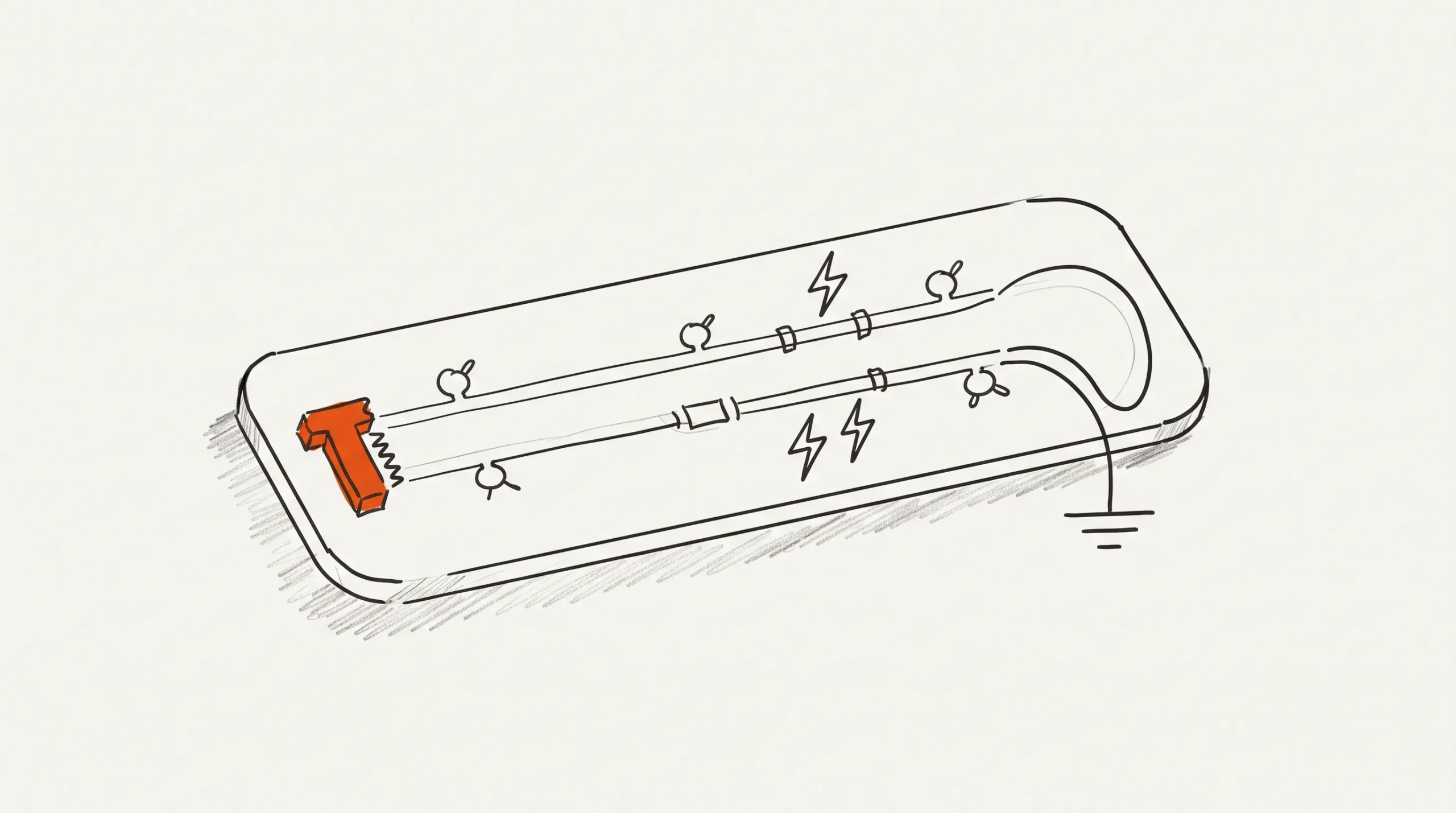
CAN termination goes at both ends of the bus and nowhere else, and it has to survive the node it is fitted to being unplugged. Get that placement right and most CAN physical-layer problems never appear. Get it wrong and the bus works on the bench, then fails in the enclosure.
Most CAN layout advice stops at “terminate the bus”. That hides the part that actually breaks boards. Termination is a property of the bus as a system, and the layout must make sure it survives field changes, hot swaps and a node pulled for diagnosis.
CAN is a vehicle bus standard that lets microcontrollers and devices communicate without a central host computer, prioritising reliability and determinism over raw speed (CAN bus). A controller on a robot arm in a factory talks to a sensor while a motor starter switches nearby, and the message must arrive intact or not at all. That priority is why the physical layer is conservative, and Texas Instruments’ Introduction to the Controller Area Network (CAN) application report says so plainly: ISO 11898 defines a single line of twisted-pair cable, terminated at both ends with 120 ohm resistors matching the characteristic impedance of the line, and placing RL on a node must be avoided because the bus loses termination if the node is disconnected.
Where termination goes, and when to split it
Most CAN standards specify a single twisted-pair cable, shielded or unshielded, with a 120 ohm characteristic impedance, and resistors equal to that impedance terminate both ends to prevent signal reflections. That is the rule stated in debugging the CAN physical layer.
Termination may be built into the cable, into a terminating node, or into the nodes at each end, and the choice is not free: the bus has to keep its termination when the equipment changes. As the same paper puts it, if nodes may be removed from the bus, the termination must be placed carefully so it is not removed with them. Without the resistive load of the CAN termination, signal integrity is compromised and the bit timing fails.
| Option | How it is built | What it does | When to use it |
|---|---|---|---|
| Single 120 ohm resistor at each end | One 120 ohm resistor across the pair at each physical end of the bus. | Matches the characteristic impedance and absorbs the wave coming back down the cable. | Fixed installations where end nodes are never unplugged. |
| Termination on the cable, not the board | The 120 ohm load sits in a connector, terminator plug or harness block. | Keeps the resistive load on the bus when a node is unplugged. | Test benches, vehicle harnesses, field-serviceable kit. |
| Split termination with a coupling capacitor | Two 120 ohm resistors in series across the pair, centre tap to ground through a capacitor. | Terminates the bus and filters common-mode energy at transmission edges. | Emissions-sensitive installations or higher signalling rates. |
| Termination on a removable node | The 120 ohm resistor sits on the PCB of a node a user can unplug. | Removes the bus termination the moment that node is unplugged. The bus runs at the wrong impedance, reflections return, and the bit timing fails. | Do not do this. Move the termination to the cable or to a fixed node. |
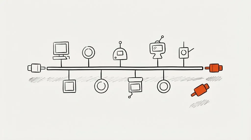
A termination is a promise about the bus that every node on it depends on. Any design that lets a user break that promise has moved a system problem onto a PCB and called it a component.
Split termination replaces the single resistor with two resistors and a capacitor. The resistors still provide the resistive load across the pair, and the capacitor from the centre tap to ground gives common-mode current somewhere to go instead of pushing it down the cable as emission.
The capacitor value is signalling-rate-dependent, and this is where people copy numbers without thinking. Texas Instruments gives the typical value for a high-speed CAN bus as 4.7 nF, which generates a 3 dB point at 1.1 Mbps. Read that as a starting point tied to a rate.
The second reason to use it is emissions. Split termination improves the electromagnetic emissions behaviour of the network by eliminating fluctuations in the bus common-mode voltages at the start and end of message transmissions. The TCAN4420 layout guidelines describe the same arrangement from the transceiver side and note that it provides common mode filtering.
Where the protection goes and why direction matters
CAN nodes live at the edge of a board, at a connector, in an environment full of switching energy. The question is not whether to protect the bus but where the protection sits and which way the energy flows.
The TCAN4420 layout guidelines are direct: design the bus protection components in the direction of the signal path, and do not force the transient current to divert from the signal path to reach the protection device. If the TVS array sits at the transceiver and the connector is far away, the transient crosses unprotected copper to reach the device meant to stop it.
Protection and filtering circuitry goes as close to the bus connector as possible, to prevent transients, ESD and noise propagating onto the board. Put the connector at the board edge, the TVS array and any common-mode choke immediately behind it, and keep the protected pair short. Supply connections matter too: the same guidance says to use at least two vias for supply (VCC) and ground connections of bypass capacitors and protection devices, to minimize trace and via inductance.

The transceiver ground reference is a layout decision
Everything above assumes the transceiver is looking at the right thing. A CAN receiver does not measure the bus against the ground of the bus, it measures it against its own ground reference. In the quiescent recessive state the two lines are passively biased to approximately 2.5 V each, and the common-mode voltage is only rejected if the reference tracks it.
So the transceiver’s ground connection is not a power wiring detail. It is the reference against which every bit on the bus is interpreted. Where it returns to the connector ground through a long path shared with a switching regulator, the reference moves as the regulator load changes and the receiver sees a common-mode step it cannot reject. The symptom is a bus that works at low current and fails when the neighbour switches.
That ground path should be short, wide and continuous, and should not share a narrow neck with high-current returns. Where the connector sits at the edge of a multi-layer board, the connector-side pour is the natural reference.
Isolation changes the problem rather than removing it. An isolated CAN interface has a barrier, and the transceiver on the bus side references the bus-side ground, not the logic-side ground. We have built a node around that split reference, on the Teensy 4.0 based CAN transceiver board in our portfolio.
Checking the board once it is laid out
A CAN layout can be reviewed against a short list before it is built, and most checks take minutes. When we take on a PCB design review, the physical-layer checks are what clients want covered.
- Confirm both ends of the bus carry a resistive load, and that no other node does.
- Ask whether any node holding a termination can be unplugged by a user. If yes, the termination belongs on the cable or on a fixed node.
- Check the distance from the connector to the protection devices. If the transient has to cross the board, the layout has the problem the TVS was meant to solve.
- Follow the transceiver ground back to the connector-side ground, and check it does not share a narrow neck with a switching return.
- Confirm the capacitor value against the signalling rate, and that the pair runs as a pair over continuous reference plane.
On the bench, start with the power off and the nodes disconnected. Measure across the pair at each end of the bus and confirm the value matches the terminations present. A reading well above the expected value means a terminator is missing; a reading near zero means a short. Then power up and watch the common-mode voltage while traffic flows.
Manufacturability sits alongside this: connector footprints, protection device spacing, via counts and the width of the bus pair all need to survive fabrication. We run that as part of a design for manufacture review, because a layout that pushes the fabricator past a limit comes back as a change nobody wanted. Our services overview covers how the two fit together.
Frequently asked questions
Where does CAN termination go?
At both ends of the bus, and never in a node that can be unplugged, because without the resistive load of the CAN termination, signal integrity is compromised and the bit timing fails. If nodes come and go, put the termination on the cable or on a fixed node.
What is split termination and when do I need it?
Two resistors with a capacitor at the centre tap to ground, giving common mode filtering for the bus. Use it when emissions are marginal, common-mode noise is the problem, or signalling rates are higher. The typical coupling capacitor for a high-speed CAN bus is 4.7 nF, which generates a 3 dB point at 1.1 Mbps, and that value is signalling-rate-dependent, so check it against your bus speed.
What values do I use for CAN termination?
120 ohm to match the characteristic impedance of the twisted pair, fitted at both ends of the bus. Resistors equal to that impedance prevent signal reflections.
How should I protect a CAN bus from ESD?
Put the protection as close to the connector as possible and in the direction of the signal path, so the transient current is diverted at the connector rather than travelling across the board. Do not force the transient current to divert from the signal path to reach the protection device. Use at least two vias for the supply and ground connections of bypass capacitors and protection devices to minimize trace and via inductance.
Why does my CAN bus work on the bench and fail in the enclosure?
Almost always the common-mode voltage, the return path, or the difference between an isolated bench setup and an installed one with real grounds. Start with the physical layer checks: measure the bus termination resistance with the power off and the nodes disconnected, then check the transceiver connections, the ground reference to the connector-side ground, and the common-mode voltage while traffic runs and neighbours switch.
What to do next
If you want a second opinion on a CAN layout you have already drawn, send us the files. Our industrial control project category covers the boards where these decisions get made.
Send four things and we can tell you quickly whether the layout needs work: the transceiver part number, the bus speed, whether the node can be removed from the bus, and whether the design has to survive isolation. The Teensy 4.0 based CAN transceiver project shows how these decisions come together on a built board. If you want it designed rather than reviewed, request a quote at pcbrouting.com/get-a-quote/.