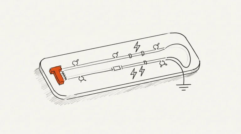
A PCB design review is an independent check of a finished design against the fabricator’s actual capabilities and the product’s own requirements, carried out before you commit money to boards. It costs hours. It catches the things a rule check cannot see: a broken return path, a plane split under a memory net, a design that passes every design rule and still fails an EMC pre-scan.
That distinction matters, because the failure mode of an unreviewed design is rarely a crash. It is a board that arrives, powers up, works on the bench, then misbehaves in the enclosure, on the production line, or later on when a lot has drifted. By then a respin is the fix, and it costs fabrication, assembly, shipping and weeks of schedule.
A review is a comparison, not an error count
The most common misunderstanding about design review is that it is a more thorough design rule check. It is not. A DRC compares geometry against a rule set, and it can only be as good as the rules it was given. A review compares the complete design against an approved capability set. That is the framing in Altium’s own PCB layout review checklist: the useful review is not a list of rule results but a judgement about whether the design can be made as drawn and will behave as the product requires.
A DRC report tells you the layout obeys the rules. A review tells you whether the rules were the right rules, and whether anything in the design is quietly fighting the product.
The checklist alone is also not enough. The review items that apply to every design are a floor, not a ceiling. Thermal reliefs show why: a missing thermal relief and an unnecessary one are both defects, and no rule set distinguishes them without knowing what the pad does electrically. Above that floor sit design-specific items the generic list does not carry: high-speed designs, bottom-terminated parts, dense via and pin fields, and multi-board assemblies each bring their own problems.
What a review covers
Before we look at any files, we agree the scope. Different areas of a design carry different consequences, and a review that treats a stackup decision with the same weight as a BOM typo is either wasteful or inadequate. The table below is the scope we work through, with the right-hand column written as consequences.
| Review area | What we check | What it catches when it is missed |
|---|---|---|
| Schematic and component selection | Part choice against the requirement, footprint accuracy, pin mapping | A design that is electrically wrong before a track is poured |
| Placement and partitioning | Where each functional block sits, hot spots, keep-outs | A prototype that needs a hacksaw, and a layout needing a respin |
| Return path and plane continuity | Where return current flows, plane splits, stitching | Emissions that fail an EMC pre-scan, with no rule violations |
| High-speed routing and length matching | Length matching against the interface spec, plane choice | A link that will not lock, or locks at a different grade than the datasheet promises |
| Power integrity and decoupling | Loop area, plane geometry under the switch node, capacitor placement | Rail collapse blamed on the sensor when the fault is the return path |
| Thermal management | Copper area under the hot part, thermal vias, heat spreading | A part over its case temperature once the enclosure is fitted |
| Isolation and safety separation | Creepage and clearance across the barrier, a reference per domain | A board that passes functional test but fails the safety scan |
| Manufacturability (DFM) | Pad and via geometry against the fabricator’s capability | A quote well above budget, or boards that come back shorted |
| Assembly and test points | Placement head clearance, polarity, probe access | A board that is untestable in production |
| Documentation and release package | Layer stack, drill tables, netlist, BOM, drawings | Boards that arrive with no record of how they were built |

If all you need checked is whether the board can be built, that is a smaller and cheaper job, and we run it as a separate pass. The DFM review service covers geometry against your fabricator’s capability document and nothing else. A full review starts from the schematic.
The circuit comes before the layout
Texas Instruments states the sequencing point more directly than most vendors do. In its High Speed Layout Guidelines application report, a good layout starts with the circuit design, and the most important aspect of component placement is where each functional block sits. Decoupling improves circuit function; bad placement damages the layout however clean the routing looks.
Return current and loop area
The TI report is blunt about it: an electrical circuit must always be a closed loop. Return current has to be accounted for, and a return path that is implied rather than drawn is one you have not controlled. A plane split under a fast edge, a change of reference plane across a layer transition, a ground pour that is not actually stitched: all of these look like a finished board and behave like an antenna. This is where the high-speed design work matters most.
Termination
TI’s report lists the common approaches, series, parallel, Thevenin and AC termination, and shows the overshoot and undershoot damage a high-impedance receiver suffers when left unterminated. That damage is not visible in a design rule report. A receiver can be correctly terminated on the schematic, correctly populated, and still be damaged if the series element sits in the wrong place relative to the driver, or if the return path is not what the termination assumes. Termination is a review item because it depends on the loop.
The question a design rule check cannot answer is not whether the board is legal. It is whether the design still behaves the way the product needs it to behave, once the enclosure is fitted, the lot has drifted, and the temperature has moved.
Isolation and stacked domains
Some designs change the rules of the review, and isolation is the clearest example. TI’s report on How to Improve Speed and Reliability of Isolated Digital Inputs in Motor Drives walks through a complete front end: a host controller, an optocoupler, a 24 V sensor or switch, and a Schmitt trigger buffer. The point is not the circuit. It is that an isolated design has two supply domains, and a review that checks one ground reference against the other is wrong.
That has practical consequences. Creepage and clearance across the barrier are measured in the direction the barrier actually runs, not in the direction the copper happens to take. Each domain needs its own return reference, and the reference for the field side does not come from the host side, however convenient the pour would make it. A board with a barrier has to be reviewed twice, once per domain.

Our broader approach is set out on the services overview, and boards we have taken through this kind of work are in the project portfolio.
Frequently asked questions
When is a design review worth the cost?
Run the arithmetic. A review is a matter of hours. A respin is fabrication, assembly, shipping and a schedule already promised to someone. It is worth doing on any board you have not prototyped before, and it is most valuable when the design came from someone else, or came from a reference design that was never re-checked against your own interfaces. A reference design answers the question its author was asking, which is not necessarily yours.
What files do I need to send for a review?
Send the schematic, or the netlist plus the parts list. Send the layout files, the BOM, the mechanical drawing, and the fabrication drawing if one exists. Send the fabricator’s capability document, because a review against the wrong capability set is only half a review. And send a written list of what you are worried about. That last one matters more than people expect: it lets us spend our time on the parts of the design you are actually nervous about.
Is a DRC clean design a good design?
No. A DRC compares geometry against a rule set, and a rule set cannot know your return path, your stackup, or your product requirements. It cannot know that the thermal relief on that pad is unnecessary, or that the isolation barrier has been crossed by a fillet, or that the termination value is right for the driver but not for the return path it assumes. The TI guidance is that a good layout starts with the circuit design, so a review that never looks at the circuit has skipped the part that decides whether the board works. Clean is the absence of one class of error, not the presence of correctness.
Can a review be done from Gerbers alone?
Yes, but it is worth less. Gerbers and the drill file give us geometry, which is useful for the manufacturability and assembly areas of the table above. What they do not give us is the stackup, the intended reference planes, the net classes, or the design intent. Without those we can tell you the board is drawn correctly and cannot tell you why. If Gerbers are all you have, say so and we will scope the review to what those files support.
How long does a review take and what do I get?
You get a findings list, not a verdict. Every finding is located on the board, prioritised by what it would cost you if it shipped, and accompanied by the reasoning behind it, so you can judge it against your own product rather than take our word for it. We also state what we did not cover and why, because a review that reads as complete when it is partial is worse than no review. Scope, turnaround and format are on the review service page.
What to send, and what a review can honestly tell you
If you are about to commit to a board, the sensible order is: send the schematic and the layout, send the fabricator’s capability document, and tell us the things that worry you most. We will tell you what we find, what is worth changing, and what we would leave alone.
Be clear about the limit of what you are buying. A review cannot tell you the design works. It can tell you that nothing obvious is wrong, that the obvious things have been checked against a real capability set rather than a generic checklist, and that the findings which would have cost you a respin have been found while the fix is still a change in the CAD file rather than a change in the mask set. That is a narrower claim than a guarantee, and it is the honest one. Request a review at the quote page, or read more at the review service page.
For the record: a printed circuit board is a mechanically supported conductive pattern, and the design you send us is the pattern plus the intention behind it. The intention is the part worth checking.